Filter and oil supply method applying filter

A filter and filter tank technology, applied in the field of filters, can solve the problems of lack of accurate sequential control logic and time sequence, stuck fuel switching valve, and low reliability, so as to improve user experience and reliability , Improve the effect of work reliability

Active Publication Date: 2021-06-22
SHANGHAI FLEETGUARD FILTER
View PDF5 Cites 0 Cited by
  • Summary
  • Abstract
  • Description
  • Claims
  • Application Information

AI Technical Summary

Problems solved by technology

[0003] In order to achieve fuel switching, the main solution adopted by vehicles on the market is to install a fuel switching valve behind the fuel tank, and manually or automatically activate the switching valve to complete the fuel switching. However, the fuel switching valve often has problems such as sticking and wear. , low reliability; at the same time, there is no accurate sequential control logic and time sequence between the switching of the fuel switching valve into the fuel tank and the switching of the fuel tank, resulting in the fuel in the common rail system and other pipelines returning to the grade that does not correspond to it In the fuel tank of the low-grade fuel tank, there is a phenomenon of oil mixing in the low-grade fuel tank, and the vehicle cannot be started with low-grade fuel. In addition, in the prior art, a filter tank is usually used to filter different fuels, and oil mixing is also prone to occur

Method used


Image

  • Filter and oil supply method applying filter
  • Filter and oil supply method applying filter
  • Filter and oil supply method applying filter

Examples


Embodiment 1

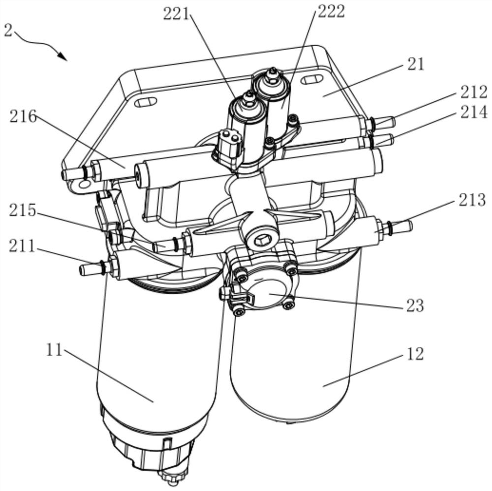
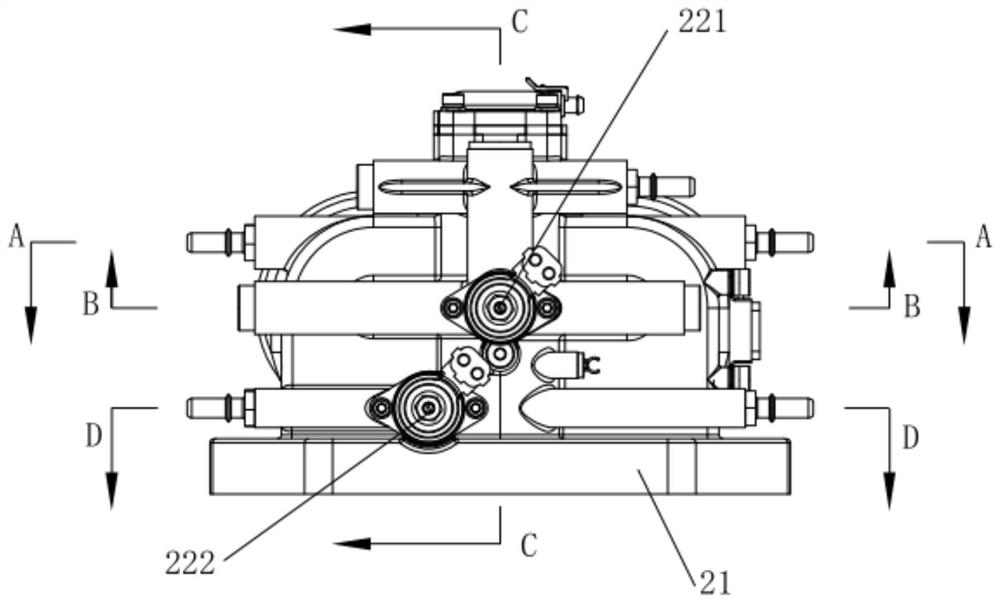
[0051] This embodiment provides a filter, such as figure 1 As shown, it includes an assembly unit 2 and a first filter tank 11 and a second filter tank 12 arranged side by side. The assembly unit 2 includes a base 21, and the first filter tank 11 and the second filter tank 12 are fixed to the base 21. Setting, the base 21 is provided with a first oil inlet pipe 211, a first oil return pipe 212, a second oil inlet pipe 213, a second oil return pipe 214 and an oil outlet pipe 215, specifically, the first oil inlet pipe 211 can communicate with the first filter tank 11 and the main fuel tank; the first oil return pipe 212 can communicate with the main fuel tank and the fuel common rail; the second oil inlet pipe 213 can communicate with the second filter tank 12 and the auxiliary fuel tank; the second oil return pipe 214 can communicate with the auxiliary fuel tank and the fuel common rail; the oil outlet pipe 215 can The low-pressure oil pump is used to communicate with the firs...

Embodiment 2

[0085] This embodiment provides a filter, and the overall structure of the filter provided by this embodiment is basically the same as that of the filter in Embodiment 1, only some settings of the control valve group are different, and this embodiment is no longer The same structure as that of the first embodiment will be described in detail.

[0086] like Figure 7 As shown, the difference between this embodiment and Embodiment 1 is that the oil inlet control valve and the oil return control valve respectively include two one-way valves 224, and each one-way valve 224 is respectively arranged on the first oil inlet pipe 211 and the first oil return pipe. 212, on the second oil inlet pipe 213 and the second oil return pipe 214, that is, the first oil inlet pipe 211, the first oil return pipe 212, the second oil inlet pipe 213, the second oil return pipe 214 and the outlet pipe are respectively connected through four check valves 224. The oil pipes 215 are controlled independe...


PUM


Abstract

The invention discloses a filter and an oil supply method applying the filter, and belongs to the technical field of filters. The filter comprises an assembly unit, a first filter tank and a second filter tank, the first filter tank and the second filter tank are arranged in parallel, the assembly unit comprises a base and a control valve set arranged on the base, the first filter tank and the second filter tank are both fixedly arranged with the base, and a first oil inlet pipe, a first oil return pipe, a second oil inlet pipe, a second oil return pipe and an oil outlet pipe are arranged on the base. The first oil inlet pipe can communicate with the first filter tank and the main oil tank; the first oil return pipe can communicate with the main oil tank and a fuel common rail; the second oil inlet pipe can communicate with the second filter tank and an auxiliary oil tank; and the second oil return pipe can communicate with the auxiliary oil tank and the fuel common rail. The oil outlet pipe can be used for communicating a low-pressure oil pump with the first filter tank and the second filter tank respectively; and the control valve set is used for controlling on-off of the first oil inlet pipe, the first oil return pipe, the second oil inlet pipe and the second oil return pipe. According to the filter and the oil supply method applying the filter, the oil return precision is improved, and oil mixing is prevented.

Description

technical field [0001] The invention relates to the technical field of filters, in particular to a filter and an oil supply method using the filter. Background technique [0002] Due to the viscosity-temperature characteristics of diesel itself, diesel engines cannot be started with high-grade (0#) diesel when the ambient temperature is low, but low-grade (-35#) diesel can be used for low-temperature start. However, low-grade diesel The price is relatively high, so commercial vehicles with diesel engines are generally equipped with main and auxiliary fuel tanks. The main fuel tank is filled with high-grade diesel, and the auxiliary fuel tank is filled with low-grade diesel. In winter or in a low-temperature environment, low-grade fuel is used to supply fuel when the vehicle is started, and the high-grade fuel is heated to a certain temperature before switching to a high-grade fuel tank for fuel supply, thereby reducing the cost of use. [0003] In order to achieve fuel swit...

Claims


Application Information

Patent Timeline
Patent Type & Authority Applications(China)
IPC IPC(8): F02M37/32F02M37/00
CPCF02M37/32F02M37/0023F02M37/0047F02M37/0052
Inventor 韩旭李蕾何骁卢增彩袁建军
Owner SHANGHAI FLEETGUARD FILTER
Why Eureka
Try Eureka