Speed limiting and braking device applied to wind driven generator and using method thereof

A technology for wind power generators and braking devices, which is applied to the control of wind power engines, wind power engines and devices that convert solar radiation into useful energy, wind power engines, etc. Poor stability and other issues, to achieve the effect of reducing heat accumulation and facilitating heat dissipation

Active Publication Date: 2021-06-22
嘉兴南湖学院 +1
View PDF14 Cites 1 Cited by
  • Summary
  • Abstract
  • Description
  • Claims
  • Application Information

AI Technical Summary

Problems solved by technology

In the wind power generator speed limiting device, when the fan blade is disturbed by strong wind, the telescopic cylinder, connecting rod, speed limiting head and anti-skid sleeve are arranged, and the telescopic cylinder is started, so that the connecting rod drives the speed limiting head to move the rotating rod to the rotating rod. For speed limit, the anti-slip sleeve can increase its friction force, making the speed limit process faster, and the support rod and connecting platform can ensure the stability of its telescopic cylinder, making the speed limit head more stable, and it is equipped with a locking block and a sliding rod And the ring block, during the speed limiting process, the sliding rod also slides in the card slot with the movement of the connecting rod, which can effectively prevent the connecting rod from shaking, making the speed limiting device more stable and more convenient However, the device fails to take into account the secondary utilization of the passing wind resources when it is working, resulting in a low utilization rate of wind resources and a low power generation efficiency of the device;
[0006] 3. The comparative document CN209800172U discloses a speed reduction device for a wind power generator, "including a wind power generator body and a speed reduction device, the speed reduction device is connected to the wind power generator body, and the wind power generator body includes a base, a support column and a shell body, the outer surface of the base, the supporting column and the housing are all provided with an anti-corrosion layer, the housing is provided with a generator, a blade assembly and an empennage, the empennage is provided with a lightning protection device, and the blade assembly includes a turntable , blades and a rotating shaft, one end of the rotating shaft is connected to the generator, and the other end is connected to the turntable, the blades are provided with a plurality of and connected to the turntable respectively, the rotating shaft and the generator are installed inside the housing, the speed reduction device Including the speed sensor, PLC controller, small cylinder and lower pressure plate, the design of the deceleration device can well protect the blade and prevent it from being damaged due to excessive speed", but the device fails to take into account the external parts of the device during the working process In the face of strong wind, the frontal contact area of ​​the external parts and the strong wind can be changed by turning to reduce the impact of strong wind blowing, thus resulting in poor installation stability of the external parts of the device

Method used


Image

  • Speed limiting and braking device applied to wind driven generator and using method thereof
  • Speed limiting and braking device applied to wind driven generator and using method thereof
  • Speed limiting and braking device applied to wind driven generator and using method thereof

Examples


Embodiment Construction

[0035] The following will clearly and completely describe the technical solutions in the embodiments of the present invention with reference to the accompanying drawings in the embodiments of the present invention. Obviously, the described embodiments are only some, not all, embodiments of the present invention. Based on the embodiments of the present invention, all other embodiments obtained by persons of ordinary skill in the art without making creative efforts belong to the protection scope of the present invention.

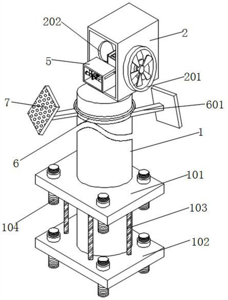
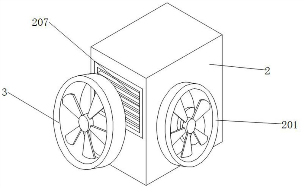
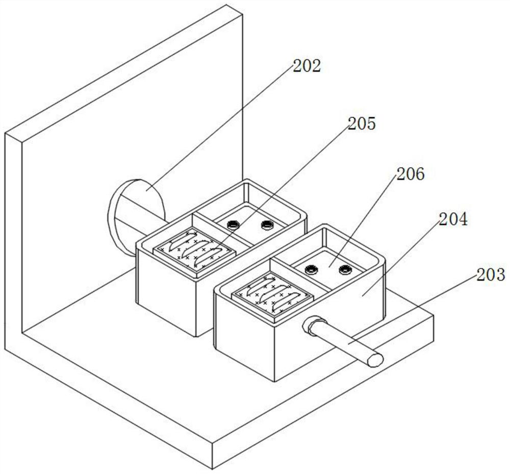
[0036] see Figure 1-Figure 8 , an embodiment provided by the present invention: a speed-limiting and braking device applied to wind-driven generators and its use method, including installing a cylinder 1, a main generator fan 3, a rotating rod 4 and a photoelectric installation box 7, and installing a cylinder 1 A secondary generator box 2 is installed on the top surface of the cylinder, and the installation column 1 can ensure the stability of its bottom ins...


PUM


Abstract

The invention discloses a speed limiting and braking device applied to a wind driven generator and a using method thereof. The speed limiting and braking device comprises a mounting cylinder, a rotating rod and photoelectric mounting boxes, wherein a secondary generator box is mounted on the surface of the top of the mounting cylinder, a speed limiting and braking box is mounted in the secondary generator box, a second generator is mounted on the bottom wall in the speed limiting and braking box, the input end of the second generator is connected with a rotating rod, the top of the surface of the mounting cylinder is sleeved with a wind power resisting ferrule, a chassis is mounted at the top of the wind power resisting ferrule, two transverse rods are connected to the interior of the chassis through sliding grooves in an embedded mode, and each photoelectric mounting box is connected to a port of the end, far away from the chassis, of the corresponding transverse rod. According to the speed limiting and braking device, the speed limiting and braking box is arranged, the rotating speed in the device is sensed through the temperature, and then speed limiting treatment on the device is achieved through magnetic force hindering; electric telescopic rods are used for encircling and fixing the rotating rod subjected to speed reduction, and therefore the braking purpose is achieved; and convenience and high efficiency are achieved.

Description

technical field [0001] The invention relates to the technical field of wind power generators, in particular to a speed limiting and braking device applied to wind power generators and a method for using the same. Background technique [0002] Wind generators are mostly installed in wide plains with rich wind resources. Driven by the prevailing wind force, the wind blades on the surface of the device can be rotated, which in turn drives the rotor inside the generator to rotate, and the induced current is generated through electromagnetic induction to complete the process. Power generation operation, but when the wind speed is fast, the fan blades rotate too fast, the resulting induced current increases, and the internal temperature of the coil increases, resulting in an increase in the internal temperature of the wind turbine, which poses a hidden danger to the safety of the internal circuit of the generator , so it is necessary to perform corresponding speed limit and brake ...

Claims


Application Information

Patent Timeline
Patent Type & Authority Applications(China)
IPC IPC(8): F03D7/02F03D80/60F03D9/11H02S20/30H02S40/42H02J7/35H02P3/06H05K7/20
CPCF03D7/0276F03D7/0244F03D80/60F03D9/11F03D9/007H02S20/30H02S40/425H02J7/35H02P3/06H05K7/20127Y02E70/30Y02E10/76Y02E10/50Y02E10/72
Inventor 刘青松岳晋萍檀宗正程海玉王璇
Owner 嘉兴南湖学院
Why Eureka
Try Eureka