Self-locking positioning anti-return valve

An anti-return, valve technology, applied in valve details, valve device, valve operation/release device, etc., can solve the problems of self-locking valve valve structure complex, inability to regulate and control the medium flow, and inability to accurately control the flow, etc. The overall shape is simple and beautiful, the positioning is stable and accurate, and the positioning accuracy is high.

Inactive Publication Date: 2021-06-22
贺玲
View PDF0 Cites 2 Cited by
  • Summary
  • Abstract
  • Description
  • Claims
  • Application Information

AI Technical Summary

Problems solved by technology

[0005] The purpose of the present invention is to provide a self-locking anti-return valve to solve the problem that most of the valves proposed in the background technology do not have a self-locking function when in use, resulting in false opening or closing or valve switch back, and the flow rate cannot be accurate. Control, self-locking valve The valve structure is complex, inconvenient to use, and cannot accurately adjust and control the flow of the medium

Method used


Image

  • Self-locking positioning anti-return valve
  • Self-locking positioning anti-return valve
  • Self-locking positioning anti-return valve

Examples


Embodiment Construction

[0028] The following will clearly and completely describe the technical solutions in the embodiments of the present invention with reference to the accompanying drawings in the embodiments of the present invention. Obviously, the described embodiments are only some, not all, embodiments of the present invention. Based on the embodiments of the present invention, all other embodiments obtained by persons of ordinary skill in the art without creative efforts fall within the protection scope of the present invention.

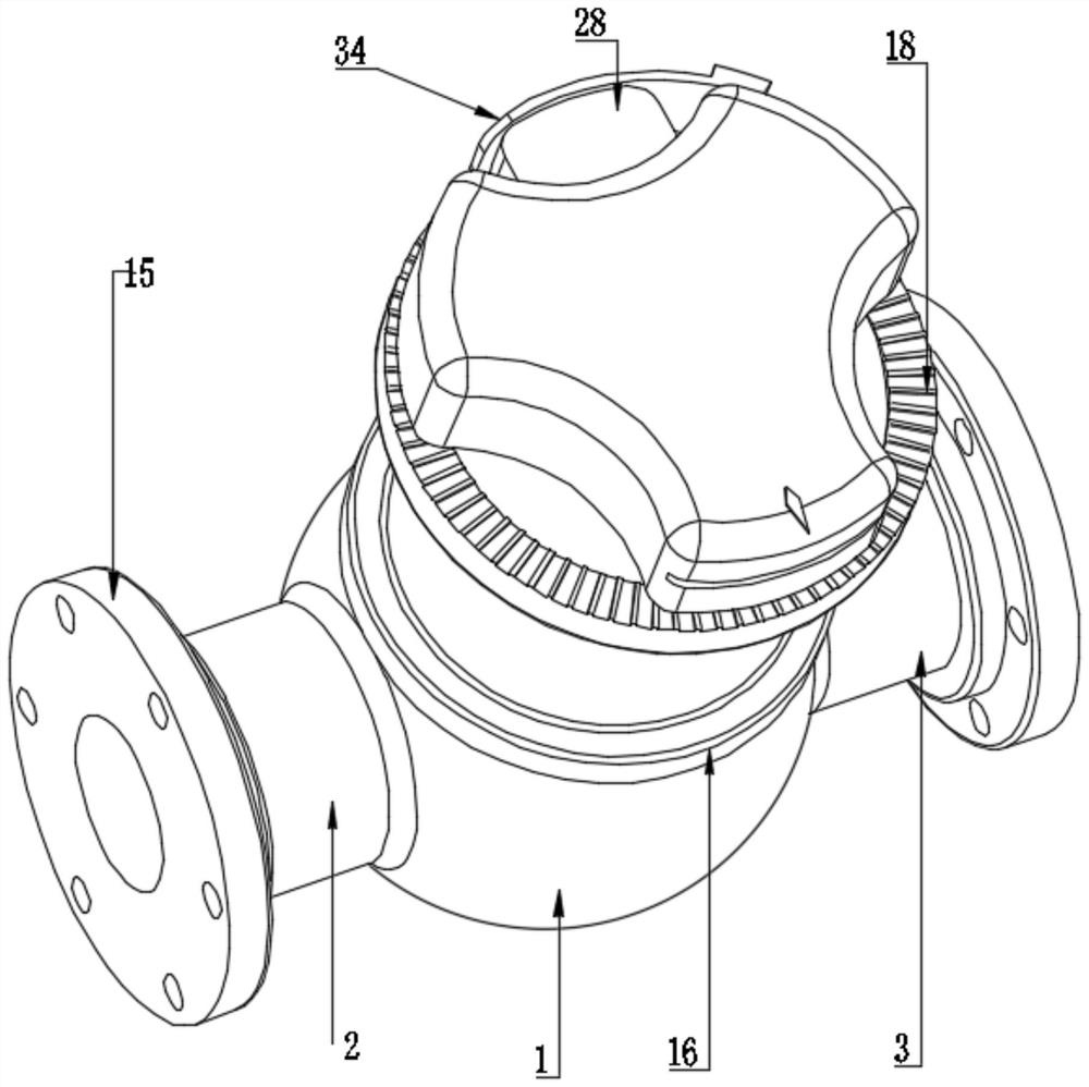
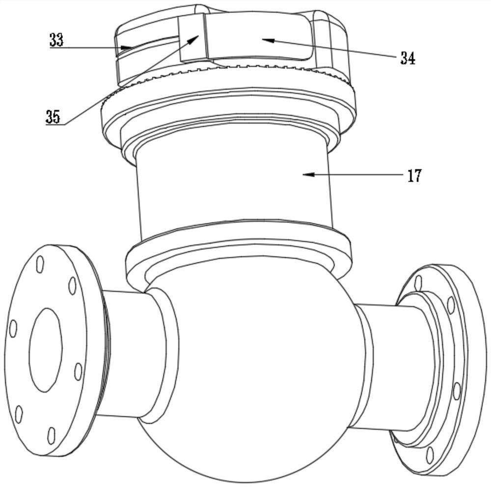
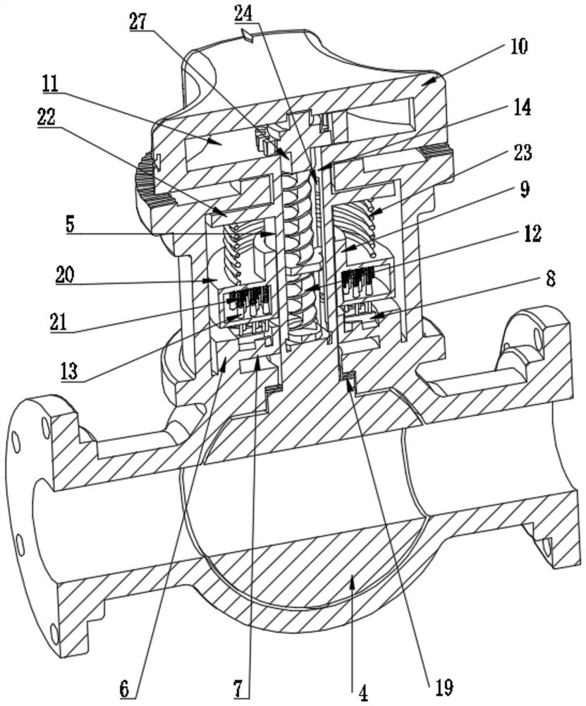
[0029] see Figure 1-6 , the present invention provides a technical solution:

[0030] A self-locking anti-retraction valve, including a valve body 1, the two sides of the valve body 1 are respectively connected with an inlet pipe 2 and a discharge pipe 3, and the middle of the valve body 1 is rotatably connected with an opening and closing valve ball 4, and the middle of the opening and closing valve ball 4 A connecting channel is opened and communicated with the...


PUM


Abstract

The invention discloses a self-locking positioning anti-return valve of the technical field of valves. The self-locking positioning anti-return valve comprises a valve body, wherein an opening and closing valve ball is rotationally connected to the middle of the valve body, and a valve rod is fixedly connected to the top of the opening and closing valve ball; a positioning ring is fixedly connected to the top of the valve body, and a positioning disc is fixedly connected to the inner wall of the positioning ring; a plurality of positioning battens are fixedly connected to the top of the positioning disc; a sliding ferrule is slidably connected to the outer wall of the valve rod, a plurality of positioning clamping needles are elastically connected to the bottom of the sliding ferrule, and a reset assembly is arranged between the valve rod and the sliding ferrule; a linkage pipeline is arranged in the middle of the valve rod, a screw rod is rotationally connected to the middle of the linkage pipeline, and the screw rod is matched with the sliding ferrule; a hand wheel is fixedly connected to the top of the valve rod, and a mounting inner chamber is formed in the middle of the hand wheel; and an unlocking assembly is elastically arranged in the middle of the mounting inner chamber. According to the self-locking positioning anti-return valve, unlocking and positioning of the valve rod is realized, return or misoperation of the opening and closing valve ball is avoided, steady flow is ensured, and the valve performance is improved; and positioning is stable and accurate, and use and adjustment are fast and simple.

Description

technical field [0001] The invention relates to the technical field of valves, in particular to a self-locking anti-return valve. Background technique [0002] Valves are widely used in all walks of life in industrial production and life. They are indispensable devices for domestic water pipelines and industrial fluid pipelines. Valves are mechanical devices that control the flow, flow direction, pressure, temperature, etc. of flowing fluid media. Devices, valves are the basic components in the piping system. Valves and fittings are technically the same as pumps, and are often discussed as a separate category. Valves can be operated manually or by handwheels, handles or pedals, and can also be controlled to change the flow of the fluid medium. Pressure, temperature and flow change, the valve is a control component in the pipeline fluid delivery system, it is used to change the passage section and the flow direction of the medium, and has the functions of diversion, cut-off, ...

Claims


Application Information

Patent Timeline
Patent Type & Authority Applications(China)
IPC IPC(8): F16K35/00F16K35/10F16K31/60
CPCF16K31/60F16K35/00F16K35/10
Inventor 贺玲
Owner 贺玲
Why Eureka
Try Eureka