Display panel and display device

A display panel and display area technology, applied in the direction of nonlinear optics, instruments, optics, etc., can solve the problems of diffraction, photo and video display quality effects, etc., to achieve the effect of increasing transmittance, improving imaging effect, and increasing the amount of incoming light

Active Publication Date: 2021-06-22
XIAMEN TIANMA MICRO ELECTRONICS
View PDF9 Cites 10 Cited by
  • Summary
  • Abstract
  • Description
  • Claims
  • Application Information

AI Technical Summary

Problems solved by technology

However, because the light still needs to pass through the display panel to reach the camera, there will still be some problems in the photos or videos taken by the camera, such as diffraction after the light passes through the display panel, which will affect the display quality of the photos and videos taken. There is an urgent need for those skilled in the art to come up with a solution

Method used


Image

  • Display panel and display device
  • Display panel and display device
  • Display panel and display device

Examples


Embodiment Construction

[0036] The embodiments of the present invention will be clearly and completely described below in conjunction with the accompanying drawings in the embodiments of the present invention. Obviously, the described embodiments are only some of the embodiments of the present invention, not all of them. Based on the embodiments of the present invention, all other embodiments obtained by persons of ordinary skill in the art without making creative efforts belong to the protection scope of the present invention.

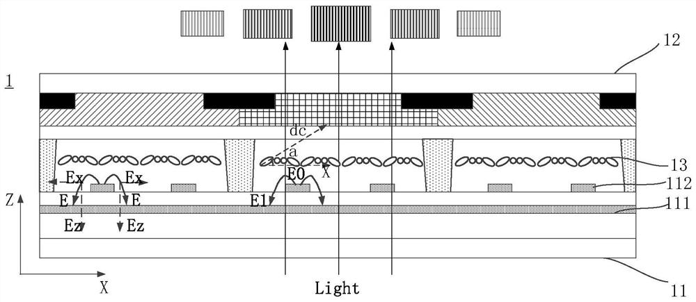
[0037] Please refer to figure 1 , figure 1 A cross-sectional schematic diagram of the display panel under liquid crystal deflection in the existing design; figure 1 Among them, a display panel 1 provided by the existing design includes an array substrate 11 and a color filter substrate 12 disposed opposite to each other, and a liquid crystal layer 13 located between the array substrate 11 and the color filter substrate 12, wherein the array substrate 11 is provided with a ...


PUM

PropertyMeasurementUnit
lengthaaaaaaaaaa

Abstract

The invention provides a display panel and a display device. The display panel comprises a first display area, the first display area comprises a plurality of sub-pixel units, a protruding part is arranged in the first display area, the orthographic projection of the protruding part on the display panel is overlapped with the sub-pixel units, the protruding part is provided with a first side edge and a second side edge, a first driving electrode is arranged on the first side edge, and a second driving electrode is arranged on the second side edge; in the same sub-pixel unit, the first driving electrode and the second driving electrode are alternately arranged, and when different potential signals are applied to the first driving electrode and the second driving electrode, a horizontal electric field is formed between the first driving electrode and the second driving electrode; the liquid crystal molecules in the liquid crystal layer rotate in the horizontal electric field, the liquid crystal molecules do not generate obvious periodical inclination and torsion arrangement, the diffraction phenomenon generated by periodical arrangement of light through liquid crystal deflection is greatly weakened, and therefore the imaging effect is improved.

Description

technical field [0001] The present invention relates to the field of display technology, in particular to a display panel and a display device. Background technique [0002] The rapid development of display technology has brought extraordinary experience to the display of information in people's life and work. People are pursuing higher and higher screen ratio of display panels. At present, display devices such as mobile phones and tablet computers often need to reserve space for commonly used front-facing cameras, infrared sensing devices, fingerprint recognition devices and other electronic photosensitive devices. Therefore, blind hole screens, notch screens, and water drop screens, which reserve space for cameras and sensing devices in the display area of ​​the display panel, emerged as the times require. [0003] However, people's pursuit of a true full screen has not stopped. More and more electronic photosensitive devices are integrated under the screen or inside the ...

Claims


Application Information

Patent Timeline
Patent Type & Authority Applications(China)
IPC IPC(8): G02F1/1343G02F1/1362
CPCG02F1/134309G02F1/134363G02F1/136286
Inventor 王海亮李雅缨杨雁周婷李俊谊
Owner XIAMEN TIANMA MICRO ELECTRONICS
Why Eureka
Try Eureka