Structure applied to common-caliber antenna body test

A common aperture, antenna technology, applied in the field of mobile communication, can solve the problems of strong inductance benefit impedance mismatch, long feeding path, inability to realize bottom feeding test scheme, etc., to avoid impedance mismatch and reduce loss.

Active Publication Date: 2021-06-22
SHENZHEN UNIV
View PDF8 Cites 0 Cited by
  • Summary
  • Abstract
  • Description
  • Claims
  • Application Information

AI Technical Summary

Problems solved by technology

[0004] 1. The low-frequency band SMA connector test scheme with a long coaxial line is no longer applicable, because it will cause large loss and strong radiation interference;
[0005] 2. The scheme of SMA connector bottom-fed microstrip transmission line is no longer applicable. One is that the SMA terminal transmitting joint commonly used in millimeter-wave antenna testing cannot realize the bottom-feed test scheme. Second, the bottom-feed method is not suitable for thicker dielectric boards. With the sharp reduction of the wavelength in the millimeter wave band, the inductance benefit introduced by the length of the probe through the dielectric plate can no longer be ignored. When the dielectric plate is thick, the strong inductance benefit introduced by the probe will lead to serious impedance mismatch;
[0006] 3. If the SMA terminal transmitting connector side-fed microstrip transmission line scheme is used in the test of the millimeter-wave antenna of the mobile phone, the feeding path is usually relatively long, which will introduce strong insertion loss
Therefore, this test scheme can only be used for the antenna design of this document, and it does not have universal applicability

Method used


Image

  • Structure applied to common-caliber antenna body test
  • Structure applied to common-caliber antenna body test
  • Structure applied to common-caliber antenna body test

Examples


Embodiment 1

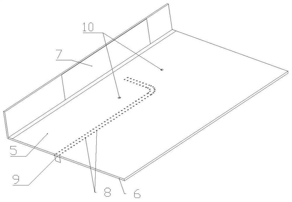
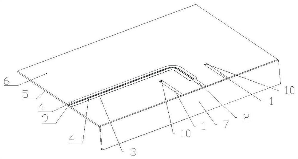
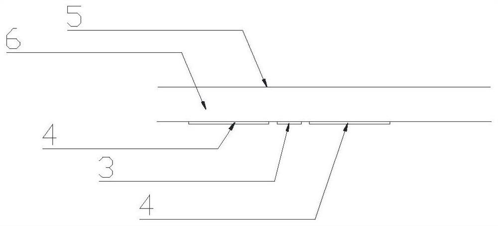
[0037] see figure 1 , figure 2 as well as image 3 , a structure applied to the common-aperture antenna body test, including a common-aperture antenna body 7, a feeding component group, a dielectric plate 6 and a metal floor 5; the common-aperture antenna body 7 includes at least one Sub-6GHz antenna and at least one Millimeter wave antenna; the feeding component group includes first feeding components whose number matches the number of Sub-6GHz antennas, and second feeding components whose number matches the number of millimeter wave antennas; the first feeding component is provided with a second A port 10 and the first microstrip line 1, the first port 10 feeds power to the Sub-6GHz antenna through the first microstrip line 1; the second feeding part is provided with a microstrip group, two A group of metal columns and a second port 9; the microstrip group is composed of a second microstrip line 2, a third microstrip line 3 and two fourth microstrip lines 4; the dielectri...

Embodiment 2

[0040] On the basis of the above structure, the distance from the first port 10 to the center of the common-aperture antenna body 7 is less than 0.5 times the distance from the second port 9 to the center of the common-aperture antenna body 7 .

[0041] Set the feed port of the Sub-6GHz antenna close to the common-aperture antenna body 7, and set the feed port of the millimeter-wave antenna away from the common-aperture antenna body 7, so that the feed ports of the two different frequency bands are far apart , to avoid signal interference between ports.

Embodiment 3

[0043] On the basis of the above structure, the length of the third microstrip line 3 is greater than twice the length of the second microstrip line 2 . When the length of the second microstrip line 2 is far less than the length of the third microstrip line 3 (that is, when the total length of the second microstrip line 2 and the third microstrip line 3 is constant, the coplanar waveguide transmission line is as long as possible), reducing The better the loss effect when the millimeter-wave antenna is fed, the better it is to ensure that the feed ports of two different frequency bands are far away from each other and do not interfere with each other.


PUM


Abstract

The invention provides a structure applied to a common-caliber antenna body test. The structure comprises a common-caliber antenna body, a feed component group, a dielectric plate and a metal floor, the common-aperture antenna body comprises at least one Sub-6GHz antenna and at least one millimeter wave antenna; the feed component group comprises first feed components of which the number is matched with that of the Sub-6GHz antennas and second feed components of which the number is matched with that of the millimeter wave antennas; the first feed component is provided with a first port and a first microstrip line, and the first port feeds the Sub-6GHz antenna through the first microstrip line; the second feed component is provided with a microstrip group, two metal column groups and a second port; the micro-strip group is composed of a second micro-strip line, a third micro-strip line and two fourth micro-strip lines; the dielectric plate is located between the metal floor and the microstrip group; the second port is located at the edge of the dielectric plate and feeds the millimeter wave antenna after passing through the third microstrip line and the second microstrip line in sequence; and the two fourth microstrip lines are respectively arranged at two sides of the third microstrip line and are respectively connected with the metal floor through a metal column group.

Description

technical field [0001] The invention relates to the technical field of mobile communication, in particular to a structure applied to the test of a common-aperture antenna body. Background technique [0002] The fifth generation of mobile communication (5G) proposes two major communication frequency bands: FR1: Sub-6GHz and FR2: millimeter wave. Although only the FR1 frequency band has been implemented in the 5G commercial process in China, Europe and other countries, the future development trend of 5G It must be developed towards millimeter wave wireless communication. This means that the coexistence of Sub-6GHz frequency band antennas and millimeter wave frequency band antennas will inevitably appear on 5G smartphones in the future. Since the space available for smartphones is getting smaller and smaller, it will be the most effective design solution to realize the Sub-6GHz frequency band antenna and the millimeter wave frequency band antenna in the way of common aperture,...

Claims


Application Information

Patent Timeline
Patent Type & Authority Applications(China)
IPC IPC(8): H01Q1/50H01Q1/48H01Q21/00H01Q21/30
CPCH01Q1/50H01Q1/48H01Q21/0006H01Q21/30Y02D30/70
Inventor 陈哲袁晓婷袁涛全智
Owner SHENZHEN UNIV
Why Eureka
Try Eureka