A kind of automatic stripping device and automatic stripping method of power cable outer protective sheath

A power cable, automatic stripping technology, applied in the direction of cable installation device, cable installation, dismantling/armored cable equipment, etc., can solve the problems of poor stripping quality, time-consuming, labor-intensive and labor-intensive, etc., achieve high regularity and reduce damage , the effect of uniform feeding

Active Publication Date: 2022-03-11
GUANGDONG TESTING INST OF PROD QUALITY SUPERVISION
View PDF0 Cites 0 Cited by
  • Summary
  • Abstract
  • Description
  • Claims
  • Application Information

AI Technical Summary

Problems solved by technology

[0006] Both the hand-held and electric hand-held peeling devices are time-consuming, labor-intensive and labor-intensive, and the peeling quality is poor

Method used


Image

  • A kind of automatic stripping device and automatic stripping method of power cable outer protective sheath
  • A kind of automatic stripping device and automatic stripping method of power cable outer protective sheath
  • A kind of automatic stripping device and automatic stripping method of power cable outer protective sheath

Examples


Embodiment 1

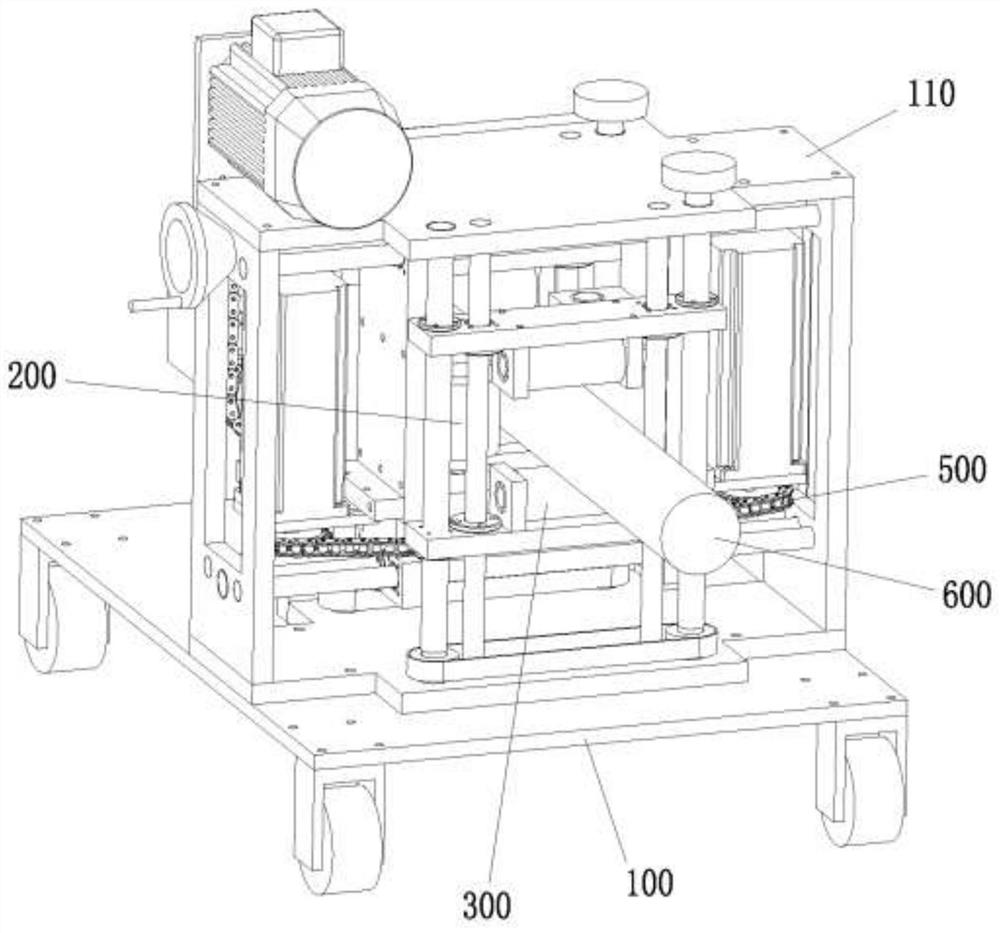
[0059] This embodiment provides a device for automatically stripping the outer protective sheath of a power cable, such as Figure 1-9 As shown, it includes a workbench 100, a feeding mechanism 200, a crimping mechanism 300 and a rotary peeling mechanism 400;

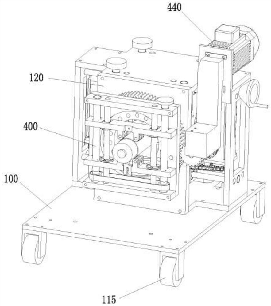
[0060] The workbench 100 comprises a support frame 110 and a fixed plate 120, the support frame 110 at least comprises a first plate 111, a second plate 112, a third plate 113 and a fourth plate 114, the first plate 111, the second plate 112, the third plate 113 and the fourth plate 114 are respectively connected to form a feed space 130, and the fixed plate 120 is located on the outlet side of the feed space 130;

[0061] The workbench 100 also preferably has a plurality of universal wheels 115 to quickly change the position, and the universal wheels 115 further have a self-locking function.

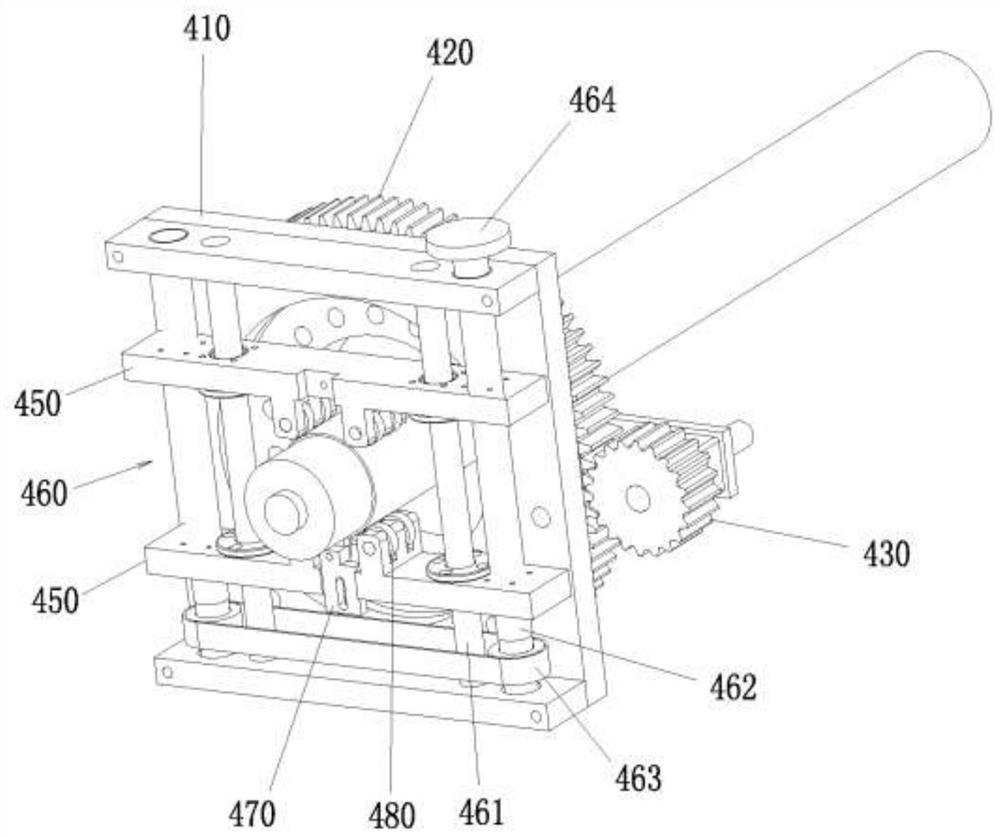
[0062] Such as Figure 3-4 As shown, the rotary peeling mechanism 400 is located on the fixed plate 120, and it includes a ro...

Embodiment 2

[0084] This embodiment provides a method for automatically stripping the outer protective sheath of a power cable, which can be realized by the automatic stripping device in Example 1, providing a support frame and having a feeding space for the power cable to pass through on the support frame, and providing a rotating frame And the rotary frame can rotate by itself, and a scraper is arranged on the rotary frame; the automatic stripping method comprises the following steps:

[0085] Crimping of power cables:

[0086] There are two sets of crimping rollers facing each other at the entrance and exit of the feeding space. The two sets of crimping rollers are located on the upper and lower sides of the power cable. The two sets of crimping rollers are driven up and down by the first screw guide assembly. Close to or separate from the back to compress the power cable, and keep the center of the power cable coincident with the center of rotation of the rotating frame;

[0087] ...


PUM


Abstract

The invention provides an automatic stripping device and an automatic stripping method for the outer protective sheath of a power cable. The automatic stripping device includes a workbench, a feeding mechanism, a crimping mechanism, and a rotary peeling mechanism; the workbench includes a supporting frame and a fixing plate, and the feeding mechanism includes two One set of feeding rollers, the two sets of feeding rollers are respectively located on both sides of the power cable and the distance between the two sets of feeding rollers is adjustable, at least one set of feeding rollers is equipped with a driving mechanism; the crimping mechanism includes two sets of crimping rollers The two sets of crimping rollers are respectively located on both sides of the power cable and the distance between the two sets of crimping rollers is adjustable; the rotary peeling mechanism includes a rotary frame, two centering pressure plates and a scraper, and the rotary frame and the fixed plate are connected in rotation , the two centering platens are slidably set on the rotating frame, and the scraper is set on the rotating frame or the centering platen; the invention adopts the way of rotation and linear compound motion to realize the automatic separation of the outer protective sheath and the core wire of the power cable, and has the advantages of stripping The advantages of good quality and high efficiency.

Description

technical field [0001] The invention belongs to the technical field of power cables, and in particular relates to an automatic stripping device and an automatic stripping method for an outer protective sheath of a power cable. Background technique [0002] When performing related testing tasks on power cables, it is necessary to peel off the outer protective sheath of the outer layer. The conventional method is to operate manually, which takes a lot of time and labor, and there are problems such as difficulty in controlling the cutting depth and poor cutting effect. [0003] The peeling device that exists on the market mainly contains two types of manual type and electric hand-held type at present. [0004] The manual cable stripping device mainly includes a handle, a cable clamping device and a cutter head assembly, etc. The guide rollers of the cable clamping device are evenly distributed on the outer wall of the cable along the circumferential direction, and the cutter he...

Claims


Application Information

Patent Timeline
Patent Type & Authority Patents(China)
IPC IPC(8): H02G1/12
CPCH02G1/1265
Inventor 刘毅林彦霆蒋建辉余荣斌
Owner GUANGDONG TESTING INST OF PROD QUALITY SUPERVISION
Why Eureka
Try Eureka