
Ceramic production waste recovery device

A technology for producing waste and recycling devices, applied in the production of ceramic materials, plastic recycling, recycling technology, etc., can solve the problems of incomplete crushing of ceramic waste, large labor input, etc., to avoid manual crushing, improve crushing quality, and improve grinding. quality effect

Active Publication Date: 2021-06-25
XUCHANG UNIV
View PDF7 Cites 4 Cited by
  • Summary
  • Abstract
  • Description
  • Claims
  • Application Information

AI Technical Summary

Problems solved by technology

[0004] In view of the above situation, in order to overcome the defects of the prior art, the present invention provides a recycling device for ceramic production waste, which effectively solves the problems of incomplete crushing of ceramic waste and large labor input in the above-mentioned background technology

Method used


Image

  • Ceramic production waste recovery device
  • Ceramic production waste recovery device
  • Ceramic production waste recovery device

Examples


Embodiment 1

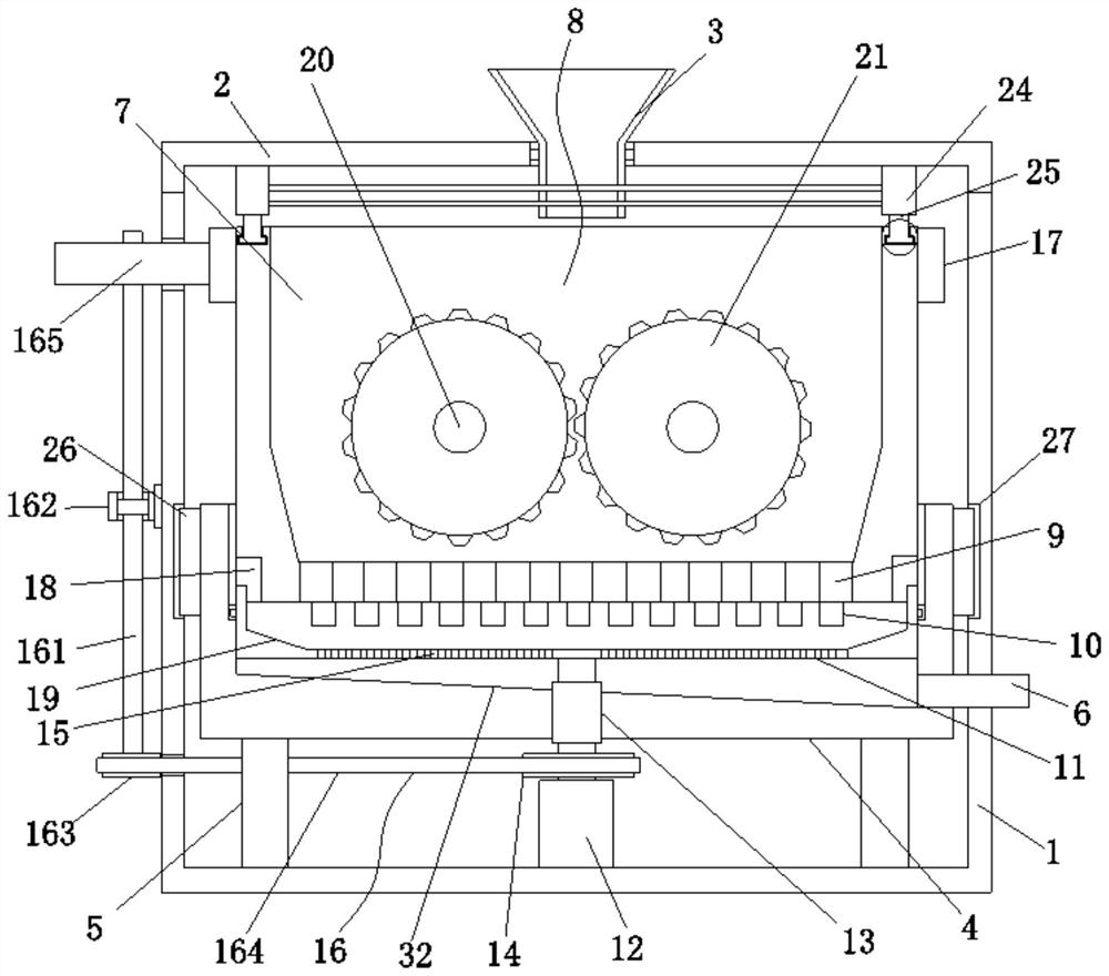
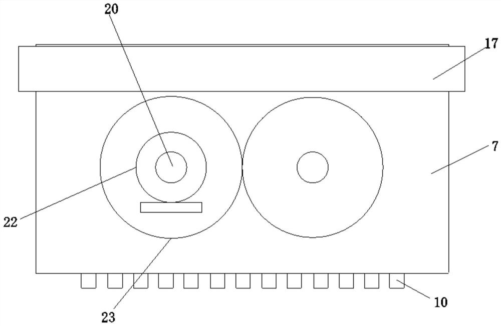
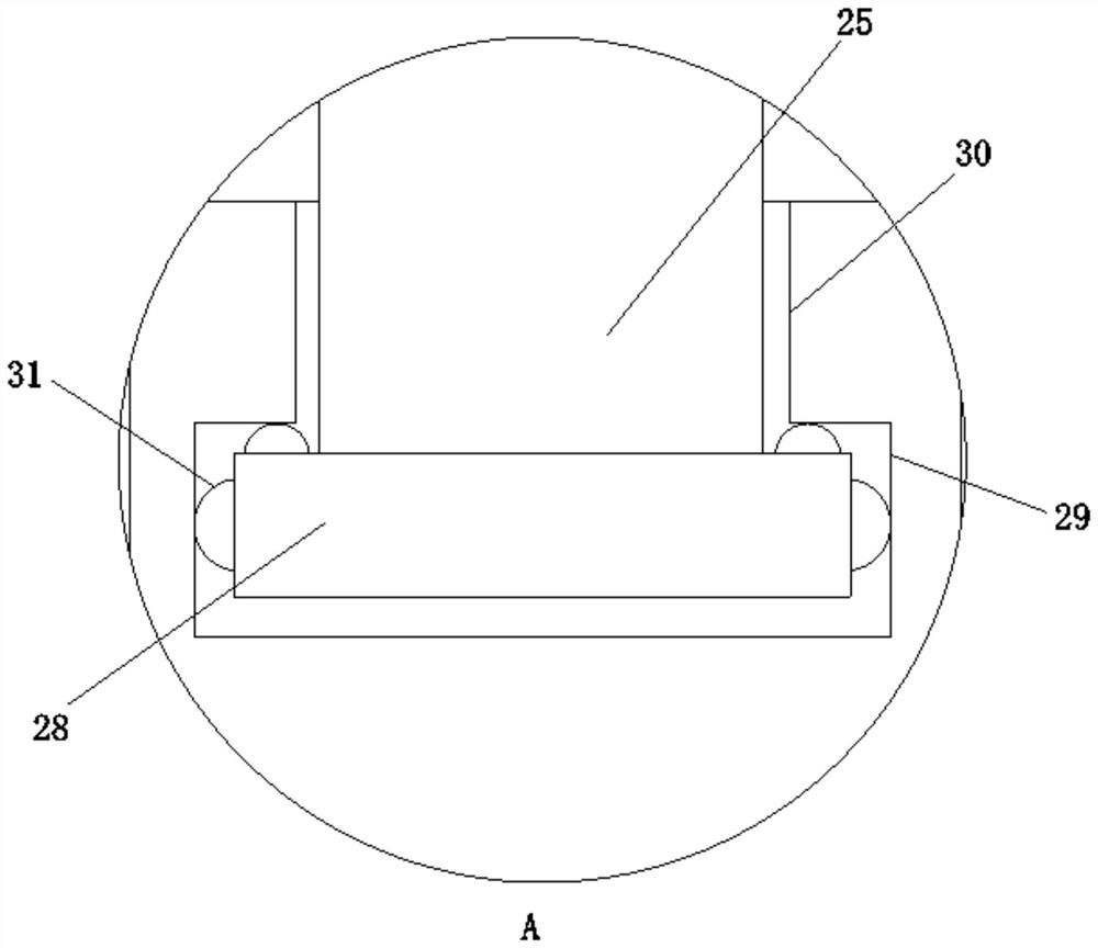
[0031] Embodiment one, by Figure 1 to Figure 6Given, the present invention comprises recovery box body 1 and recovery box cover 2, and recovery box cover 2 is installed on the top of recovery box body 1, and the top middle position of recovery box cover 2 is provided with feed inlet 3, and the inside of recovery box body 1 A discharge box 4 is provided, and the bottom of the discharge box 4 is provided with a support column 5 located at the inner bottom of the recovery box 1, and one side of the discharge box 4 is provided with a side wall that runs through the recovery box 1 and extends to the recovery box 1. The discharge pipe 6 outside the box body 1. It should be noted here that one end of the discharge pipe 6 is connected to the external suction pump. Through the design of the discharge pipe 6, it is convenient to realize the extraction of the screened waste, and the recovery box The upper part of the body 1 is provided with a crushing box 7 located at the top of the dis...

Embodiment 2

[0034] Embodiment two, on the basis of embodiment one, by figure 1 Given, the aperture of the first screening hole 9 is larger than the aperture of the second screening hole 15, and the inner wall of the grinding seat 11 is provided with a chute 19, thereby realizing the function of double screening.

Embodiment 3

[0035] Embodiment three, on the basis of embodiment one, by figure 1 Given, the inner bottom end of the discharge box 4 is provided with a material guide plate 32, the output shaft of the motor one 12 is connected with the bottom end of the discharge box 4 through a bearing sleeve 13, and the outer wall of the discharge box 4 is symmetrically provided with The stabilizer 26 and the inner wall of the recovery box 1 are provided with a stabilizing slot 27 that engages with the stabilizer 26 to control the stability of the discharge box 4 and prevent the discharge box 4 from shifting.


PUM


Abstract

The invention relates to the technical field of ceramic production, and discloses a ceramic production waste recovery device. The device solves the problems of incomplete crushing of ceramic waste and larger labor input, and comprises a recovery box body and a recovery box cover, the recovery box cover is mounted at the top end of the recovery box body, and a feed inlet is formed in the middle of the top end of the recovery box cover. A discharging box is arranged in the recovery box body, supporting columns located at the bottom end in the recovery box body are arranged at the periphery of the bottom end of the discharging box, and a discharging pipe penetrating through the side wall of the recovery box body and extending to the outside of the recovery box body is arranged at one side of the discharging box; and by arranging a smashing box, a rotating shaft, a smashing roller, a second motor and a second gear, smashing operation on ceramic waste chips is conveniently achieved, meanwhile, through the action of a grinding plate, a grinding base, a first motor, a first belt wheel, a conveyor and a first gear, secondary smashing on the waste chips is facilitated, manual smashing can be avoided, and then the smashing efficiency is effectively improved.

Description

technical field [0001] The invention belongs to the technical field of ceramic production, in particular to a recycling device for ceramic production waste. Background technique [0002] Ceramics is the general term for pottery and porcelain. It is a variety of products made of natural clay and various natural minerals as the main raw materials through crushing, kneading, molding and calcination. Defective products will appear due to manual errors. Such products are unqualified and can only be treated as waste. Currently, ceramic waste is crushed and recycled for secondary use. [0003] The current ceramic waste crushing device does not completely crush the waste, and the crushed waste is of different sizes. After the machine is processed, it needs to be screened again manually, which greatly wastes manpower and resources. Contents of the invention [0004] In view of the above situation, in order to overcome the defects of the prior art, the present invention provides a ...

Claims


Application Information

Patent Timeline
IPC IPC(8): B02C4/08B02C4/30B02C4/42B02C19/20B02C23/16B02C23/14
CPCB02C4/08B02C4/30B02C4/42B02C19/20B02C23/16B02C23/14B02C2023/165B02C2201/06Y02P40/60
Inventor 高金朋何迎冯铭华
Owner XUCHANG UNIV
Learn More