IC receiving device

A material tube and material end technology, applied in the field of chip sorting, can solve the problems of slow work efficiency and easy damage to IC chips, and achieve the effect of improving efficiency and stability, reducing control links and reducing control difficulty.

Active Publication Date: 2021-06-25
天津金海通半导体设备股份有限公司
View PDF10 Cites 3 Cited by
  • Summary
  • Abstract
  • Description
  • Claims
  • Application Information

AI Technical Summary

Problems solved by technology

[0005] In view of this, the present invention aims to propose an IC receiving material device to solve the problem that the IC chip receiving material mechanism in the prior art has slow working efficiency and the IC chip is easily damaged during the material receiving process.

Method used


Image

  • IC receiving device
  • IC receiving device
  • IC receiving device

Examples


Embodiment Construction

[0024] It should be noted that, in the case of no conflict, the embodiments of the present invention and the features in the embodiments can be combined with each other.

[0025] In describing the present invention, it should be understood that the terms "center", "longitudinal", "transverse", "upper", "lower", "front", "rear", "left", "right", " The orientations or positional relationships indicated by "vertical", "horizontal", "top", "bottom", "inner" and "outer" are based on the orientations or positional relationships shown in the drawings, and are only for the convenience of describing the present invention and Simplified descriptions, rather than indicating or implying that the device or element referred to must have a particular orientation, be constructed and operate in a particular orientation, and thus should not be construed as limiting the invention. In addition, the terms "first", "second", etc. are used for descriptive purposes only, and should not be understood ...


PUM


Abstract

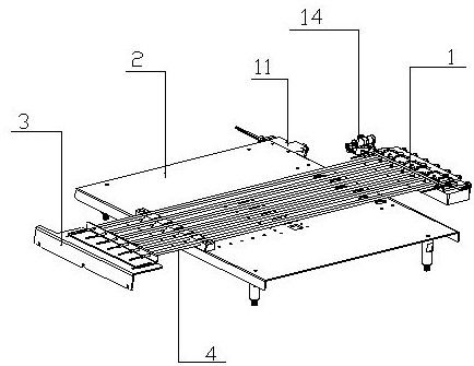
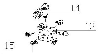
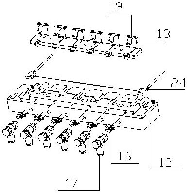
The invention provides an IC receiving device. The IC receiving device is characterized in that an IC receiving block is installed at one end of a material pipe bearing mechanism; a material waiting holes are formed in the upper end of the IC receiving block; one end of each material pipe is located in one material waiting hole; power flow channels are formed in the IC receiving block, and the air outlet end of each power flow channel and the feeding end of the corresponding material pipe are located on two side walls of one material waiting hole separately; vacuum flow channels are formed in the IC receiving block, and the air outlet end of each vacuum flow channel is located at the bottom of one material waiting hole; an air pump provides compressed air to the power flow channels through a high-speed switching valve; the material waiting holes are of a self-alignment structure; and the compressed air forms directional pushing of IC chips between the power flow channels and the material waiting holes, and the compressed air forms vacuum positioning of the IC chips between the power flow channels and the vacuum flow channels. According to the IC receiving device, through the matching of the power flow channels and the vacuum flow channels, original compressed air is utilized, and the work of IC high-speed material blowing and feeding is completed under the working condition that an upper cover plate is not needed, so that the product production efficiency and the product yield are improved.

Description

technical field [0001] The invention belongs to the field of chip sorting, in particular to an IC receiving device. Background technique [0002] In the field of semiconductor testing and sorting, material tubes or track-discharging receiving mechanisms are often used. The general working process of this type of receiving mechanism is as follows: the manipulator sends the IC chip into the receiving material module, the receiving material module is connected with the material tube or the track, and the IC chip is blown into the corresponding material tube through the blowing mechanism at the end of the receiving material module Or track. [0003] The track-type IC receiving mechanism in the prior art has too high requirements on the accuracy of the manipulator's discharging height, and often needs to sacrifice the speed of the whole machine to ensure the discharging height, thereby reducing the sorting efficiency of the whole machine. If the discharge height of the manipula...

Claims


Application Information

Patent Timeline
Patent Type & Authority Applications(China)
IPC IPC(8): B07C5/36B07C5/38B07C5/342H01L21/67
CPCB07C5/342B07C5/367B07C5/38B07C2501/0063H01L21/67271
Inventor 仇葳李彦樟彭煜唐泉龙盛辛未
Owner 天津金海通半导体设备股份有限公司
Why Eureka
Try Eureka