
Transmission mechanism based on mechanical rotation

A transmission mechanism and mechanical technology, applied in storage devices, metal processing equipment, feeding devices, etc., can solve problems such as inability to drive work, lack of rotational force, affecting mechanical work efficiency, etc., to increase the transmission distance and improve automation. performance, the effect of improving the scope of application of the workpiece and the processing efficiency

Active Publication Date: 2021-06-25
江苏福依特机械制造有限公司
View PDF16 Cites 0 Cited by
  • Summary
  • Abstract
  • Description
  • Claims
  • Application Information

AI Technical Summary

Problems solved by technology

[0003] When the existing mechanical equipment processes and transports workpieces, it uses the power between the mechanical transmission parts to drive the workpiece to carry out the conveying work, and the power generated by the transmission parts only has the effect of one-way force and does not have the left and right rotation force, so that After the transmission part is stretched forward, it cannot be rotated and contracted, which affects the working efficiency of the machine. This cannot continue the transmission work, and when continuous transmission work is required, the staff needs to make regular adjustments and settings on the side, which is very easy to cause The physical strength of the staff and the consumption of working time do not have the automation performance

Method used


Image

  • Transmission mechanism based on mechanical rotation
  • Transmission mechanism based on mechanical rotation
  • Transmission mechanism based on mechanical rotation

Examples


Embodiment Construction

[0026] The following will clearly and completely describe the technical solutions in the embodiments of the present invention with reference to the accompanying drawings in the embodiments of the present invention. Obviously, the described embodiments are only some, not all, embodiments of the present invention. Based on the embodiments of the present invention, all other embodiments obtained by persons of ordinary skill in the art without making creative efforts belong to the protection scope of the present invention.

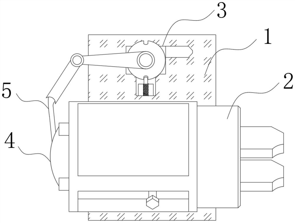
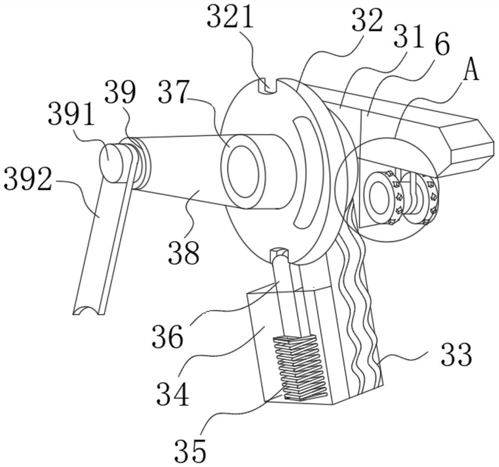
[0027] as attached Figure 1-5 The shown transmission mechanism based on mechanical rotation includes a limit mounting plate 1, the outer surface of the limit mounting plate 1 is movably fitted with a workpiece connector 2, and the top of the limit mounting plate 1 is movably set on the outer surface. There is a transmission assembly 3, a connection limit frame 4 is fixedly installed on one side of the workpiece connector 2, and a connection transmission rod 5...


PUM


Abstract

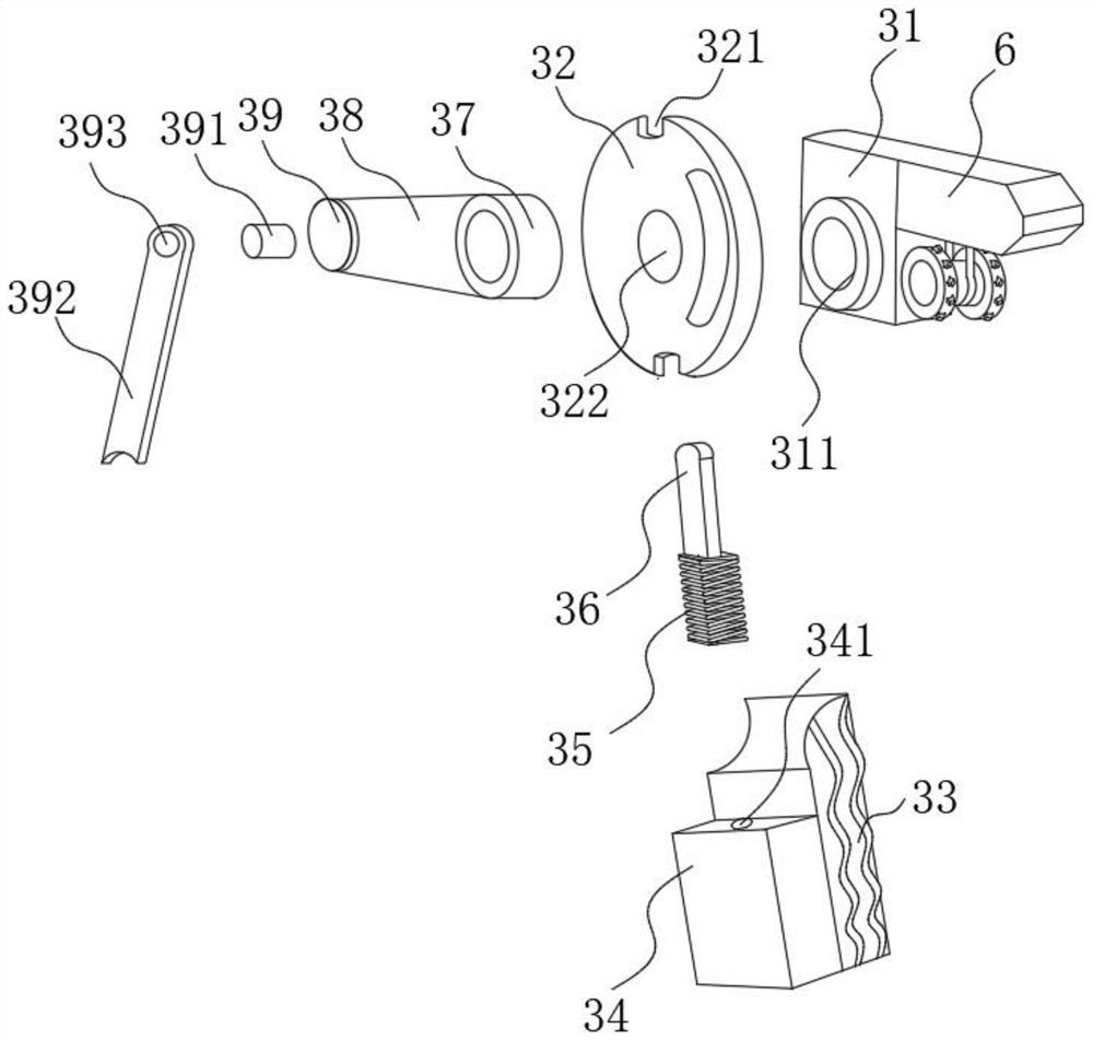
The invention discloses a transmission mechanism based on mechanical rotation. The transmission mechanism comprises a limiting mounting plate, the outer surface of the limiting mounting plate is movably sleeved with a workpiece connecting part, the top of the outer surface of the limiting mounting plate is movably sleeved with a transmission assembly, a connecting limiting frame is fixedly arranged on one side of the workpiece connecting part, a connecting transmission rod is fixedly connected to the top of the connecting limiting frame, the transmission assembly comprises a transmission base plate, the outer surface of the transmission base plate is movably sleeved with a transmission guide disc, notch grooves are formed in the upper end and the lower end of the transmission guide disc, a middle shaft hole is formed in the middle of the transmission guide disc, and the middle of the transmission base plate is movably sleeved with a driving inner disc. According to the transmission mechanism, through work driving of the transmission assembly, the connecting limiting frame, the connecting transmission rod and other assemblies, an elastic connecting supporting rod can be matched with the notch groove in the top of the transmission guide disc, so that the transmission guide disc is driven to rotate, intermittent transmission work can be conducted, and workpiece machining is facilitated.

Description

technical field [0001] The invention relates to the technical field of mechanical equipment, more specifically, the invention is a transmission mechanism based on mechanical rotation. Background technique [0002] There are many types of mechanical equipment. When the mechanical equipment is running, some of its parts and even itself can perform different forms of mechanical movement. The mechanical equipment consists of a driving device, a transmission device, a transmission device, a working device, a braking device, a protective device, a lubrication system, and a cooling system. system and other components. [0003] When the existing mechanical equipment processes and transports workpieces, it uses the power between the mechanical transmission parts to drive the workpiece to carry out the conveying work, and the power generated by the transmission parts only has the effect of one-way force and does not have the left and right rotation force, so that After the transmissi...

Claims


Application Information

Patent Timeline
Patent Type & Authority Applications(China)
IPC IPC(8): B21D43/04
CPCB21D43/04
Inventor 潘立峰
Owner 江苏福依特机械制造有限公司
Learn More