
A stable anti-drifting sundries floating tube hydroelectric power generation device

A power generation device and sundry technology, applied in hydropower, engine components, floating buildings, etc., can solve problems that affect power generation efficiency, easily damaged water wheels, and generators that cannot generate electricity

Active Publication Date: 2020-10-30
临沂联泰新型建材合伙企业(有限合伙)
View PDF4 Cites 0 Cited by
  • Summary
  • Abstract
  • Description
  • Claims
  • Application Information

AI Technical Summary

Problems solved by technology

[0005] Aiming at the deficiencies in the prior art, the purpose of the present invention is to provide a stable anti-drifting debris floating tube hydroelectric power generation device to solve the problem of being easily changed in direction by complex undercurrents and large waves in waters with turbulent and complicated water flow, resulting in The water flow does not hit the water wheel, which affects the power generation efficiency, and the situation in the water area is complicated. There are often various household garbage and deciduous branches falling from the river bank into the floating tube to entangle the water wheel, causing the water wheel to fail to rotate. The generator cannot generate electricity, and some small fish may be involved in the water wheel, which is easy to damage the water wheel

Method used


Image

  • A stable anti-drifting sundries floating tube hydroelectric power generation device
  • A stable anti-drifting sundries floating tube hydroelectric power generation device
  • A stable anti-drifting sundries floating tube hydroelectric power generation device

Examples


Embodiment Construction

[0027] In order to make the technical means, creative features, goals and effects achieved by the present invention easy to understand, the present invention will be further described below in conjunction with specific embodiments.

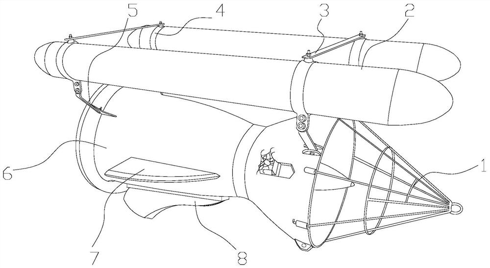
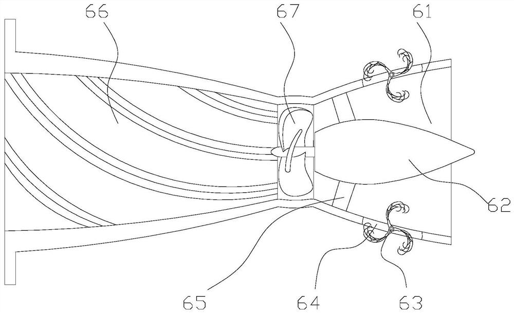
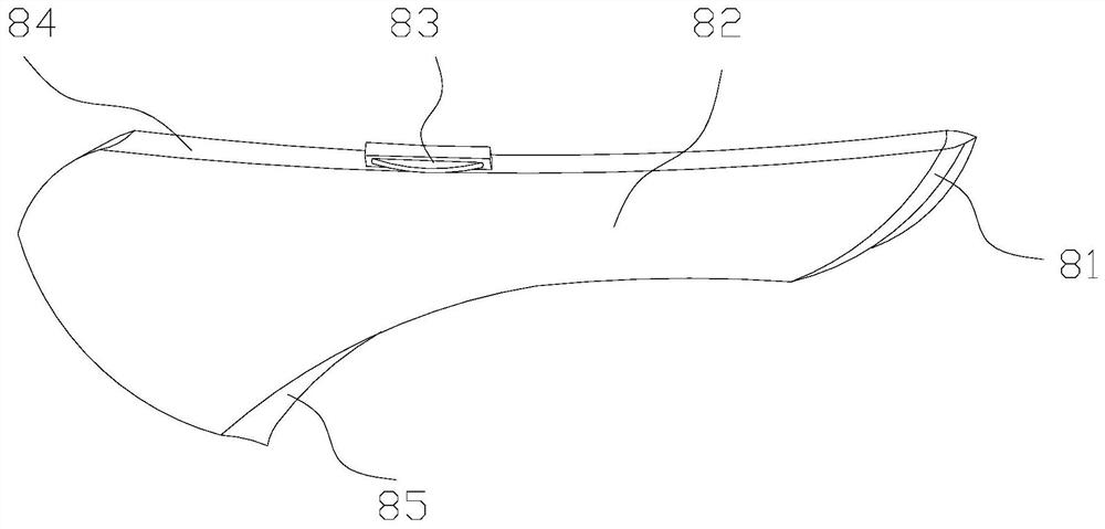
[0028] see figure 1 Summary of the invention: the present invention provides a kind of stable anti-drifting sundries floating tube type hydroelectric power generation device, its structure comprises anti-blocking cover 1, sealed floating tube 2, connecting frame 3, fixing ring 4, support 5, cylinder body 6, horizontal water diversion Plate 7, bottom water part plate 8, the left side of the anti-blocking cover 1 is nested on the outer surface of the right side of the cylinder body 6, the sealed floating tube 2 is fixed above the cylinder body 6, and the connecting frame 3 is fixed by bolts and The upper part of the ring 4 is fixedly connected, the fixed ring 4 is nested on the sealed floating tube 2 and is in interference fit with the sealed float...


PUM


Abstract

The invention discloses a stable floating-debris-preventing floating tube type hydraulic electrogenerating device which structurally comprises an anti-blocking cover, a sealing floating tube, a connecting frame, a fixing ring, a support, a barrel body, a horizontal water diversion plate and a bottom water diversion plate. The left side of the anti-blocking cover is nested to the outer surface of the right side of the barrel body, and the sealing floating tube is fixed above the barrel body. Compared with the prior art, the contact area between the device and water is enlarged on the horizontalface and the vertical face through the horizontal water diversion plate and the bottom water diversion plate, impact force of water flow on the front face of the device is reduced, the counter-actingforce of the device on water is improved, device is higher in stability, the problem that the device direction is changed, water flow cannot impact a water wheel, and power generation efficiency is affected is avoided, a rotating body has rotating force by means of accelerated water flow inside the barrel body through a water blocking plate, a water blocking block is impacted by water to enable an impurity grabbing net to be shrunk to grab small impurities and fish which penetrate through the anti-blocking cover in water flow, the small impurities and fish are thrown out through movable exhaust holes, and the rotating water wheel is prevented from being entangled or damaged.

Description

technical field [0001] The invention relates to the field of hydropower generation, in particular to a stable anti-drifting sundries floating tube type hydropower generation device. Background technique [0002] Floating tube hydroelectric generators directly use the natural advection hydropower of rivers, ocean currents, and tides. Through the internal speed-up device, the fluid speed in the tube is accelerated, and the water wheel is driven to rotate to drive the generator to generate electricity without building a dam to intercept the water flow. Height difference, close to nature, suitable for various environments, but the lack of consideration of the existing technology is: [0003] 1. In waters with turbulent and complex currents, the direction is easily changed by complex undercurrents and large waves, causing the water flow to fail to hit the water wheel and affect power generation efficiency; [0004] 2. The situation in the water area is complicated. There are oft...

Claims


Application Information

Patent Timeline
Patent Type & Authority Patents(China)
IPC IPC(8): F03B13/00F03B11/08B63B35/44
CPCB63B35/44B63B2035/4466F03B11/08F03B13/00Y02E10/20
Inventor 陈鑫
Owner 临沂联泰新型建材合伙企业(有限合伙)
Learn More