
Cleaning device

A technology for cleaning equipment and driving shafts, which is applied in the field of cleaning and can solve the problems of increased clearance between the roller brush and the shaft shoulders at both ends, axial movement of the roller brush, and time-consuming replacement of the roller brush.

Active Publication Date: 2021-06-25
GUANGDONG BOZHILIN ROBOT CO LTD
View PDF6 Cites 2 Cited by
  • Summary
  • Abstract
  • Description
  • Claims
  • Application Information

AI Technical Summary

Problems solved by technology

[0003] In order to facilitate disassembly, the roller brushes of road sweepers currently on the market adopt a structure in which the drive shaft and the driven shaft hold the roller brush at both ends respectively. There are two main problems in this structure: first, the drive shaft is under the pulling force of the outer drive pulley It will bend and deform to the outside, causing the gap between the roller brush and the shaft shoulders at both ends to increase, and the roller brush will move axially during the rotation process, causing problems such as abnormal noise and increased wear; secondly, the swing arm is fixed on the side of the driven shaft It is difficult to disassemble, and the replacement of the roller brush is time-consuming and laborious

Method used


Image

  • Cleaning device
  • Cleaning device
  • Cleaning device

Examples


Embodiment Construction

[0040] Embodiments of the present invention are described in detail below, examples of which are shown in the drawings, wherein the same or similar reference numerals designate the same or similar elements or elements having the same or similar functions throughout. The embodiments described below by referring to the figures are exemplary only for explaining the present invention and should not be construed as limiting the present invention.

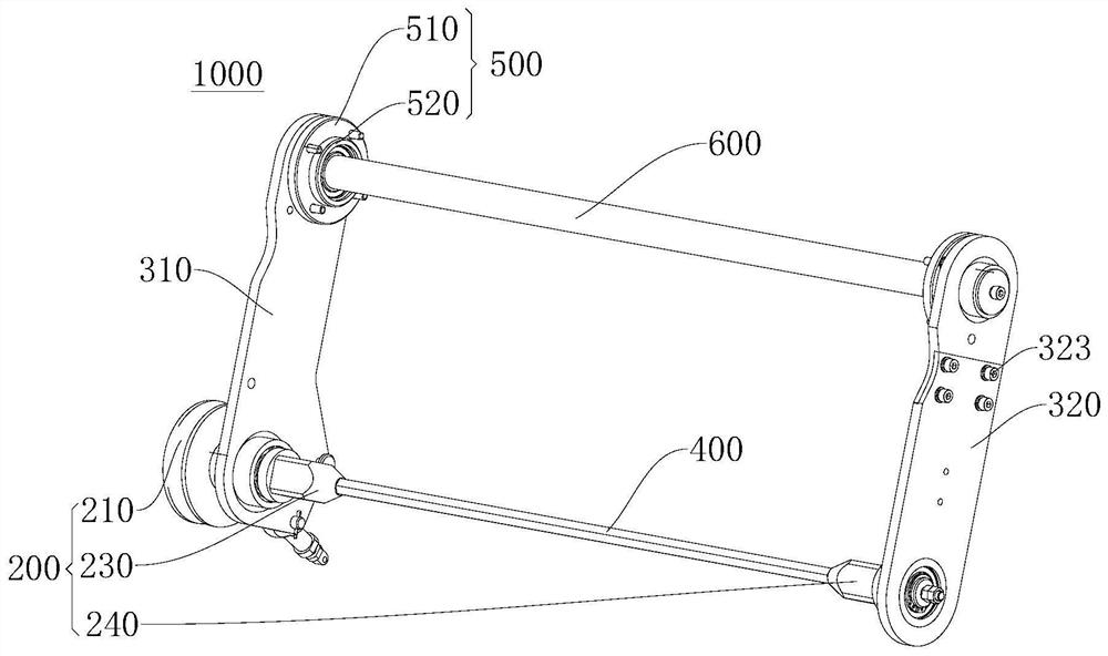
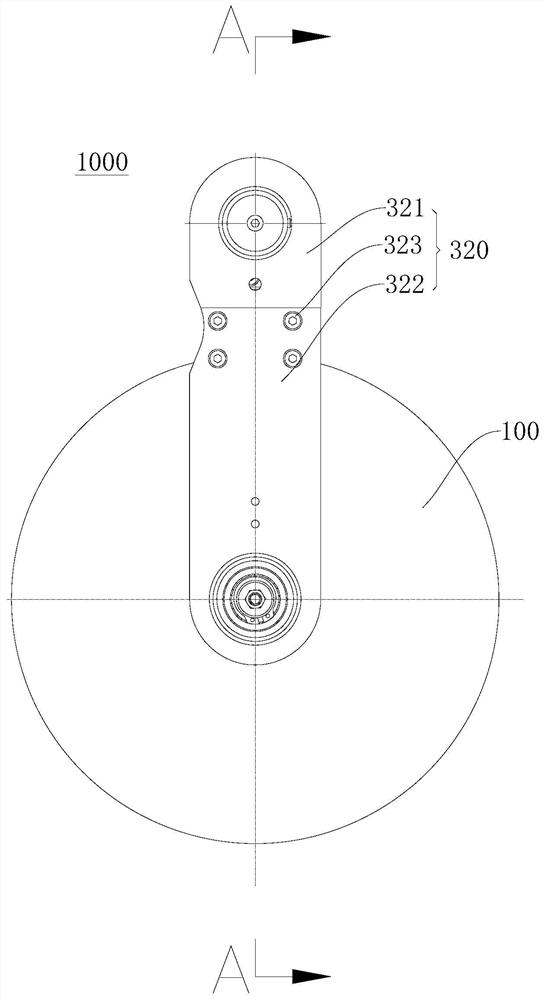
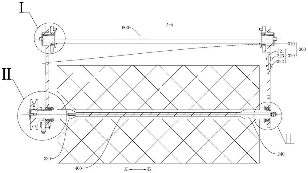
[0041] Refer below Figure 1-Figure 12 A cleaning device 1000 according to an embodiment of the present invention is described. The cleaning equipment 1000 aims to solve the time-consuming and laborious replacement and disassembly of the roller brush 100 during use, and the axial movement of the roller brush 100 caused by the side-mounted bending moment of the transmission belt during the rotation of the roller brush 100, which causes large abnormal noise and wear. exacerbated problem.

[0042] The cleaning device 1000 according to the...


PUM


Abstract

The invention discloses cleaning equipment. The cleaning equipment comprises a rolling brush, and a shaft hole penetrating through the rolling brush in the axial direction is formed in the middle of the rolling brush; the cleaning equipment further comprises a driving assembly which comprises a driving part, a flexible belt, a driving shaft and a driven shaft, the driving shaft and the driven shaft are inserted into the two ends of the shaft hole of the rolling brush respectively, shaft shoulders are arranged on the driving shaft and the driven shaft, and the driving part and the driving shaft are in transmission connection through the flexible belt; the cleaning equipment further comprises a rack which comprises a shell, a first swing arm and a second swing arm, the rolling brush is located in the shell, the first swing arm and the second swing arm are located at the two axial ends of the rolling brush, one end of the first swing arm and one end of the second swing arm are rotationally connected with the shell, and the driving shaft and the driven shaft are rotationally connected with the other end of the first swing arm and the other end of the second swing arm respectively; the cleaning equipment further comprises a tensioning piece which is located in the shaft hole, and the two ends of the tensioning piece are connected with the driving shaft and the driven shaft correspondingly, so that shaft shoulders of the driving shaft and the driven shaft abut against the two axial end faces of the rolling brush correspondingly. According to the cleaning equipment, the driving shaft and the driven shaft can be tensioned through the tensioning piece.

Description

technical field [0001] The invention relates to the technical field of cleaning, in particular to a cleaning device. Background technique [0002] In related technologies, cleaning equipment such as the roller brush of a road sweeper needs to perform high-speed rotating motion during the working process. Since the roller brush is constantly rubbing against the ground during the working process, the bristles on the roller brush will continue to wear as the working time increases. , When the bristles of the roller brush are worn to a certain extent, the worn roller brush needs to be replaced. [0003] In order to facilitate disassembly, the roller brushes of road sweepers currently on the market adopt a structure in which the driving shaft and the driven shaft block the roller brushes at both ends respectively. There are two main problems in this structure: first, the driving shaft is under the pulling force of the outer drive pulley It will bend and deform to the outside, ca...

Claims


Application Information

Patent Timeline
IPC IPC(8): E01H1/05
CPCE01H1/056
Inventor 刘昭易国春曾田
Owner GUANGDONG BOZHILIN ROBOT CO LTD
Learn More