Flow guide type inlet structure of drainage cooling section of heater and design method

A hydrophobic cooling and flow guiding technology, applied in mechanical equipment, engine components, machines/engines, etc., can solve problems such as easy destruction of the equilibrium state, fluctuations in the water level of the heater, burst pipes, etc., to avoid vapor-liquid two-phase flow Phenomenon, enhance the suction capacity of siphon, improve the effect of siphon stability

Active Publication Date: 2021-06-25
XIAN XIRE ENERGY SAVING TECH +3
View PDF7 Cites 0 Cited by
  • Summary
  • Abstract
  • Description
  • Claims
  • Application Information

AI Technical Summary

Problems solved by technology

Currently affected by factors such as power peak regulation, the operating conditions of the generator set are complex. The heater must not only operate under rated conditions, but may also be affected by various abnormal conditions. Therefore, the water level of the heater will fluctuate significantly. Fluctuation phenomenon
The commonly used cold-draining section of the heater is a single-channel planar end wall design. When the working condition changes and the water level of the heater fluctuates, the equilibrium state of the siphon structure is easily destroyed, and part of the steam in the saturated section will enter the cold-draining section. , which leads to the occurrence of vapor-liquid two-phase flow phenomenon, which increases the difference between the hydrophobic ends of the heater, which in turn intensifies the erosion of the tube wall of the next stage heater, thus making the tube wall thinner, and in severe cases, safety accidents such as tube bursts occur

Method used


Image

  • Flow guide type inlet structure of drainage cooling section of heater and design method
  • Flow guide type inlet structure of drainage cooling section of heater and design method
  • Flow guide type inlet structure of drainage cooling section of heater and design method

Examples


Embodiment Construction

[0030] The present invention will be further described below in conjunction with the accompanying drawings.

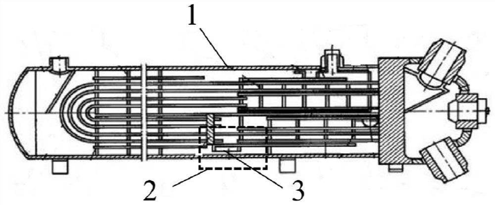
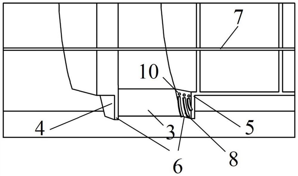
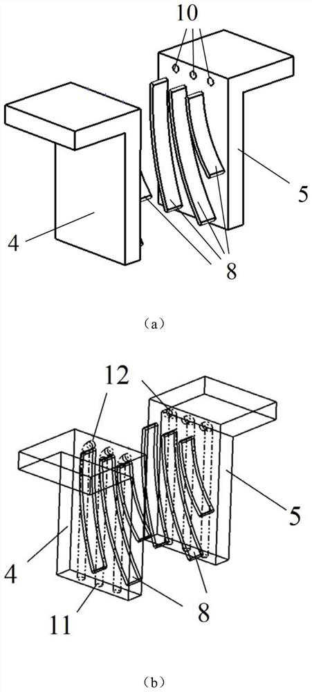
[0031] see Figure 1 to Figure 6 , a flow-guided heater hydrophobic cooling section inlet structure, including a number of guide vanes 8 arranged on the upstream hydrophobic cooling end plate 4 of the heater hydrophobic cooling section and the downstream hydrophobic cooling end plate 5 of the heater hydrophobic cooling section , the adjacent diversion cascades 8 form a diversion cascade channel 9, and the bottom of the drain cooling end plate 4 on the upstream side of the heater hydrophobic cooling section and the drain cooling end plate 5 on the downstream side of the heater hydrophobic cooling section is provided with a drainage hole inlet 11 The outlet 12 of the drainage hole is provided on the lower end surface 6 of the hydrophobic cooling end plate of the heater hydrophobic cooling section, and the outlet 12 of the drainage hole is placed on the upper part of the ...


PUM


Abstract

The invention discloses a flow guide type inlet structure of a drainage cooling section of a heater and a design method. A plurality of flow guide blade grids are arranged on an upstream side drainage cooling end plate of the drainage cooling section of the heater and a downstream side drainage cooling end plate of the drainage cooling section of the heater, so that flow guide blade grid channels with equal outlet through-flow areas are formed, drainage hole outlets are evenly formed in the upper portions of the flow guide blade grid channels, drainage hole inlets are formed in the lower end face of the upstream side drainage cooling end plate of the drainage cooling section of the heater and the lower end face of the downstream side drainage cooling end plate of the drainage cooling section of the heater, the arrangement of drainage holes fully utilizes differential pressure power at the inlets and the outlets, and drainage water in the high-pressure area at the inlet of the drainage cooling section can directly reach the inside of the drainage cooling section under the driving of the pressure gradient, so that the siphoning capacity of the drainage cooling section is further improved, and finally, the performance of a siphoning structure and the stability of a low-siphoning structure are improved.

Description

technical field [0001] The invention belongs to the field of steam turbine power generation, and in particular relates to an inlet structure and a design method of a flow-guided heater's drain cooling section. Background technique [0002] At present, the regenerative cycle is widely used in the system design of large thermal power plants, and the regenerative cycle is realized by configuring the feed water heater. The feedwater heater is an important equipment to improve the economy of thermal power plants. According to the different steam-water heat exchange methods in the feedwater heater, it is usually divided into superheating section, saturated section and cooling section in structure. The superheated section of the heater uses the sensible heat of the superheated extraction steam of the steam turbine stage to heat the feed water in the shaped pipe. After the steam is deflected in multiple ways through the partition, the superheated steam will be cooled to 25°C-30°C hi...

Claims


Application Information

Patent Timeline
Patent Type & Authority Applications(China)
IPC IPC(8): F01D25/12F01D25/00F01D21/00
CPCF01D25/12F01D25/00F01D21/003F01D21/00
Inventor 高庆郑超罗威屈杰朱蓬勃廖勇韩甲生陆明志马汀山居文平
Owner XIAN XIRE ENERGY SAVING TECH
Why Eureka
Try Eureka