
A blood sugar test strip

A technology for testing strips and blood sugar, applied in measuring devices, material analysis through electromagnetic means, instruments, etc., can solve the problems of large siphon slit cavity, incomplete siphon, and increased blood collection volume, so as to increase siphon resistance , blood circulation is smooth, and the effect of accelerating the siphon effect

Active Publication Date: 2017-01-18
海宁经开产业园区开发建设有限公司
View PDF10 Cites 0 Cited by
  • Summary
  • Abstract
  • Description
  • Claims
  • Application Information

AI Technical Summary

Problems solved by technology

This traditional rectangular chip can only siphon blood samples from one direction, and it is often necessary to set an exhaust channel behind the siphon tank to facilitate the removal of air, and the setting of the exhaust channel will inevitably increase the difficulty and cost of the manufacturing process
In addition, once the back of the siphon groove is blocked, the air cannot be removed, which will lead to incomplete siphon and affect the accuracy of the measurement results
[0003] In order to overcome this defect, Chinese patent CN2859523Y (disclosure date January 17, 2007) discloses an open type / no-resistance siphon biosensing chip, forming a gap between the substrate and the plastic sheet at the front periphery of the chip. Complete siphon slit cavity. Although the complete siphon slit cavity can solve the problem of siphon obstruction and realize multi-directional free siphon, the siphon slit cavity is relatively large and requires a large amount of blood to fill the Enzyme reaction zone to realize the measurement of blood sugar
However, increasing the amount of blood collected will inevitably increase the pain of the subject.

Method used


Image

  • A blood sugar test strip
  • A blood sugar test strip
  • A blood sugar test strip

Examples


Embodiment 1

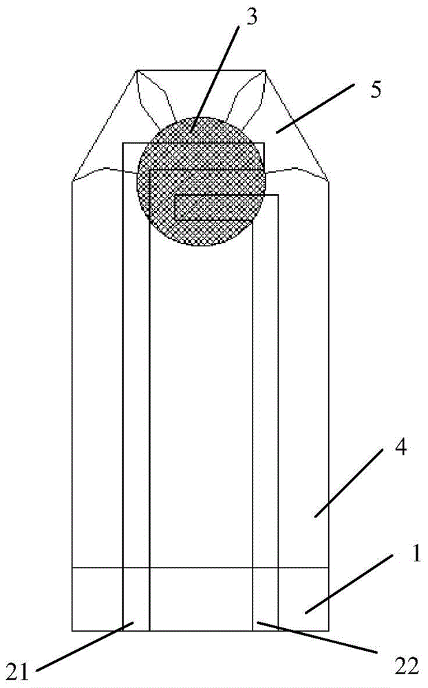
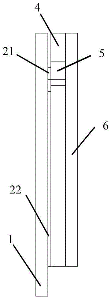
[0018] Such as figure 1 As shown, the blood glucose test strip is 35 mm long and 10 mm wide, and is provided with an upper insulating layer 6, a spacer layer 4, an enzyme reaction area 3, a working electrode 21, a reference electrode 22, and a lower insulating layer 1 from top to bottom. 6. The spacer layer 4 and the lower insulating layer 1 define a siphon cavity 5 at the front end of the test strip. One end of the siphon cavity 5 is the blood collection end, and the other end is the sample injection end that communicates with the enzyme reaction area 3. The opening of the blood collection end is larger than the injection port. The opening of the sample end. The blood collection end is trapezoidal with three openings. The surroundings of the siphon cavity 5 are coated with hydrophilic materials.

Embodiment 2

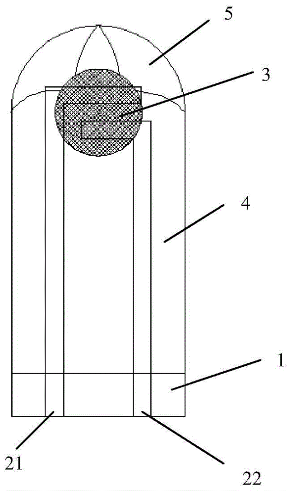
[0020] Such as figure 2 As shown, the blood glucose test strip has a length of 35mm and a width of 10mm, and is provided with an upper insulating layer 6, a spacer layer 4, an enzyme reaction area 3, a working electrode 21, a reference electrode 22 and a lower insulating layer 1 in order from top to bottom. The upper insulating layer 6, the spacer layer 4 and the lower insulating layer 1 define a siphon cavity 5 at the front end of the test strip. One end of the siphon cavity 5 is the blood sampling end, and the other end is the sampling end communicating with the enzyme reaction zone 3. The opening is larger than the opening at the injection end. The blood collection end is semicircular and has two openings. The opening of the siphon cavity 5 gradually decreases from the blood collection end to the sample injection end as an arc. The surroundings of the siphon cavity 5 are coated with hydrophilic materials.

[0021] In addition to the above-mentioned embodiments, the pres...


PUM

PropertyMeasurementUnit
widthaaaaaaaaaa

Abstract

The invention discloses a blood sugar test strip. An upper insulating layer, a separating layer, an enzyme reaction area and a lower insulating layer are sequentially arranged from top to bottom, the upper insulating layer, the separating layer and the lower insulating layer limit a siphon hollow cavity on the front end of the test strip, one end of the siphon hollow cavity is a blood collecting end, the other end of the siphon hollow cavity is a sample introduction end communicated with the enzyme reaction area, and the opening of the blood collecting end is larger than the opening of the sample introduction end. The blood sugar test strip has the advantages of being small in blood collecting quantity, capable of collecting blood in multiple directions and smooth in siphoning.

Description

technical field [0001] The invention belongs to the technical field of blood sugar testing, in particular to a blood sugar testing strip with improved structure. Background technique [0002] The structure of the traditional blood glucose test strip is that the measuring electrodes are printed on the insulating substrate, the measuring electrodes are covered with enzymes, and the upper part is covered with an insulating cover plate for protection. This traditional rectangular chip can only siphon blood samples from one direction, and it is often necessary to set an exhaust channel behind the siphon tank to facilitate the removal of air. However, the setting of the exhaust channel will inevitably increase the difficulty and cost of the manufacturing process. In addition, once the back of the siphon groove is blocked, the air cannot be removed, which will lead to incomplete siphon and affect the accuracy of the measurement results. [0003] In order to overcome this defect, C...

Claims


Application Information

Patent Timeline
Patent Type & Authority Patents(China)
IPC IPC(8): G01N27/00
Inventor 马莉
Owner 海宁经开产业园区开发建设有限公司
Learn More