Water chilling unit

A chiller, cooling water technology, applied in refrigerators, refrigeration components, subcoolers, etc., can solve the problem of not being able to significantly reduce the refrigerant charge, achieve the effect of small volume, reduce greenhouse gas emissions, and avoid liquid hammer

Inactive Publication Date: 2021-06-25
QINGDAO HAIER AIR CONDITIONING ELECTRONICS CO LTD +1
View PDF6 Cites 0 Cited by
  • Summary
  • Abstract
  • Description
  • Claims
  • Application Information

AI Technical Summary

Problems solved by technology

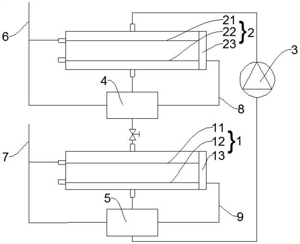
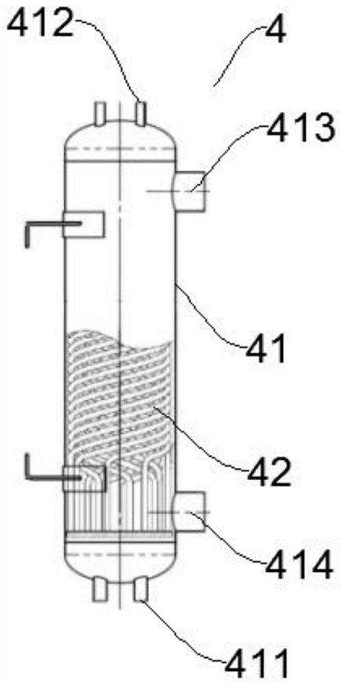
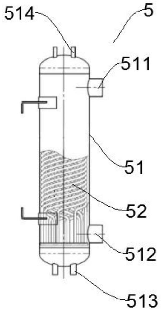
[0005] In order to solve the above-mentioned problems in the prior art, that is, in order to solve the problem that the existing chiller adopts the falling film evaporator and cannot significantly reduce the refrigerant charge, the present invention provides a chiller, which includes an evaporator, a condensing The condenser, compressor, subcooler and superheater, the condenser, subcooler, evaporator, superheater and compressor form a closed-loop refrigerant circulation circuit, and the chiller also includes the first cooling water inlet pipe and the second cooling water inlet pipe. water pipe, the first cooling water connecting pipe and the second cooling water connecting pipe, the first cooling water inlet pipe is respectively connected to the condenser and the subcooler, the first cooling water connecting pipe is connected between the subcooler and the condenser, and the second The second cooling water inlet pipe is connected to the evaporator and the superheater respectively, and the second cooling water connection pipe is connected between the superheater and the evaporator

Method used


Image

  • Water chilling unit
  • Water chilling unit
  • Water chilling unit

Examples


Embodiment Construction

[0022] Preferred embodiments of the present invention are described below with reference to the accompanying drawings. Those skilled in the art should understand that these embodiments are only used to explain the technical principles of the present invention, and are not intended to limit the protection scope of the present invention.

[0023] It should be noted that, in the description of the present invention, terms such as "middle", "upper", "lower", "inner", "outer" and other indicated directions or positional relationships are based on the directions or positional relationships shown in the drawings. The positional relationship, which is just for convenience of description, does not indicate or imply that the device or element must have a specific orientation, be constructed and operated in a specific orientation, and thus should not be construed as limiting the present invention. In addition, the terms "first" and "second" are used for descriptive purposes only, and sho...


PUM


Abstract

The invention belongs to the technical field of water chilling units, and aims to solve the problem that a falling film evaporator adopted by an existing water chilling unit cannot remarkably reduce the refrigerant filling amount. For this aim, the provided water chilling unit comprises an evaporator, a condenser, a compressor, a subcooler and a superheater, and the condenser, the subcooler, the evaporator, the superheater and the compressor form a closed refrigerant circulation loop, the water chilling unit further comprises a first cooling water inlet pipe, a second cooling water inlet pipe, a first cooling water connecting pipe and a second cooling water connecting pipe, the first cooling water inlet pipe is connected with the condenser and the subcooler, the first cooling water connecting pipe is connected between the subcooler and the condenser, the second cooling water inlet pipe is connected with the evaporator and the superheater, and the second cooling water connecting pipe is connected between the superheater and the evaporator. According to the water chilling unit, the refrigerant filling amount of the water chilling unit can be greatly reduced, and greenhouse gas emission is remarkably reduced.

Description

technical field [0001] The invention belongs to the technical field of chillers, and specifically provides a chiller. Background technique [0002] Chillers include air-cooled chillers and water-cooled chillers. In water-cooled chillers, refrigerants such as R134a (a gas with a high greenhouse effect) are widely used. Whether it is a water-cooled screw unit or a water-cooled maglev unit, it needs A large amount of refrigerant charge can ensure the normal operation of the system. Usually, the charge amount of refrigerant is 200kg to 1000kg. In the water-cooled screw unit and water-cooled maglev unit, about 90% of the refrigerant is distributed in the evaporator and condenser. By reducing the refrigerant charge in the system, greenhouse gas emissions can be significantly reduced. [0003] In the prior art, the way to reduce the refrigerant charge is to convert the traditional flooded evaporator into a falling film evaporator. This method can reduce the refrigerant charge of t...

Claims


Application Information

Patent Timeline
Patent Type & Authority Applications(China)
IPC IPC(8): F25B1/00F25B40/02F25B40/06F25B49/02
CPCF25B1/00F25B40/02F25B40/06F25B49/02F25B2500/28F25B39/00F25B40/00
Inventor 任滔柴婷宋强王冰
Owner QINGDAO HAIER AIR CONDITIONING ELECTRONICS CO LTD
Why Eureka
Try Eureka