Direct shear box for studying mechanical properties of contact surface
A technology of mechanical properties and contact surface, applied in the direction of strength properties, using stable shear force to test the strength of materials, scientific instruments, etc. Data and other issues to achieve the effect of improving the release effect
- Summary
- Abstract
- Description
- Claims
- Application Information
AI Technical Summary
Problems solved by technology
Method used
Image
Examples
no. 1 example
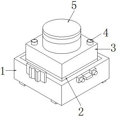
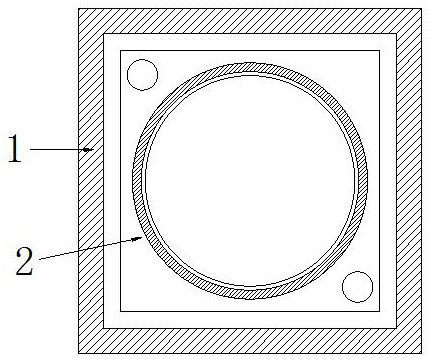
[0029] Such as Figure 1-Figure 6 As shown, the present invention provides the technical scheme of the direct shear box for studying the mechanical properties of the contact surface:
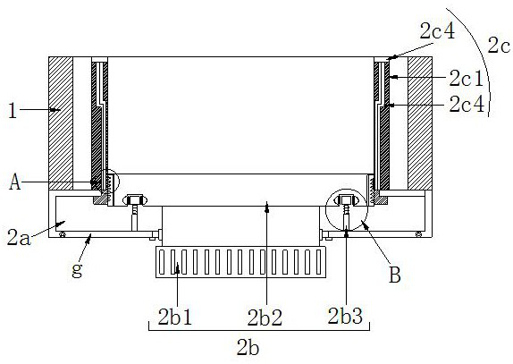
[0030] Such as Figure 1-Figure 3 As shown, the direct shear box used to study the mechanical properties of the contact surface includes a shell 1, a lower shear box 2, an upper shear box 3, a sheath hole 4, and a pressure plate 5. The lower shear box 2 is set on the shell 1 Inside, the upper shear box 3 is located above the lower shear box 2, and is fixed with the sheath hole 4 and the sheath bar. The pressure plate 5 is arranged on the upper middle of the upper shear box 3 and installed correspondingly. The lower shear box 2 includes Hollow cavity 2a, demoulding aid mechanism 2b, and seepage absorption structure 2c, the hollow cavity 2a is installed on the lower surface of the lower shear box 2, the demoulding aid mechanism 2b is arranged in the middle of the lower shear box 2, and the lower ...
no. 2 example
[0040] Such as image 3 , Figure 5 As shown, the present invention provides the technical scheme of the direct shear box for studying the mechanical properties of the contact surface:
[0041] Such as image 3 As shown, the direct shear box used to study the mechanical properties of the contact surface has a structure including a movable plate g on the lower surface of the hollow cavity 2a, and the movable plate g cooperates with the hollow cavity 2a through a hinge, which is beneficial to realize the After the seepage structure 2c becomes saturated with the absorbed seepage water, it cooperates with the movable plate g to replace it in time.
[0042] Such as Figure 4 As shown, the seepage absorption structure 2c includes a ring wall 2c1, a convex thread 2c2, a channel 2c3, a suction ring pad 2c4, a drainage strip 2c5, and a water-absorbing sealing ring 2c6. The convex thread 2c2 is installed on the lower part of the inner ring of the ring wall 2c1, and Cooperating with ...
PUM
 Abstract
Description
Claims
Application Information
 - R&D
- Intellectual Property
- Life Sciences
- Materials
- Tech Scout
- Unparalleled Data Quality
- Higher Quality Content
- 60% Fewer Hallucinations
Browse by: Latest US Patents, China's latest patents, Technical Efficacy Thesaurus, Application Domain, Technology Topic, Popular Technical Reports.
© 2025 PatSnap. All rights reserved.Legal|Privacy policy|Modern Slavery Act Transparency Statement|Sitemap|About US| Contact US: help@patsnap.com


