Novel permanent magnet synchronous motor position observation method with dynamic error compensation function

A permanent magnet synchronous motor, dynamic error technology, applied in the direction of motor generator control, generator control, motor control, etc., can solve the problems of increasing the complexity of the drive system, reducing the reliability of the system, increasing the cost, etc. The effect of perceived performance

Pending Publication Date: 2021-06-25
SHANGHAI UNIV OF ENG SCI +1
View PDF0 Cites 2 Cited by
  • Summary
  • Abstract
  • Description
  • Claims
  • Application Information

AI Technical Summary

Problems solved by technology

In the control system of the permanent magnet synchronous motor, it is essential to install a speed sensor or a position sensor on the motor shaft, which brings the following problems: (1) The sensor is affected by temperature, humidity, detection distance, vibration and other working conditions Influence, especially in some applications with high sensor detection accuracy, limits the application of PMSM speed control system in these special fields; (2) The sensor increases the size of the motor and increases the inertia of the control system; (3) In order to ensure the detection accuracy, the in

Method used


Image

  • Novel permanent magnet synchronous motor position observation method with dynamic error compensation function
  • Novel permanent magnet synchronous motor position observation method with dynamic error compensation function
  • Novel permanent magnet synchronous motor position observation method with dynamic error compensation function

Examples


Example Embodiment

[0048] Example 1:

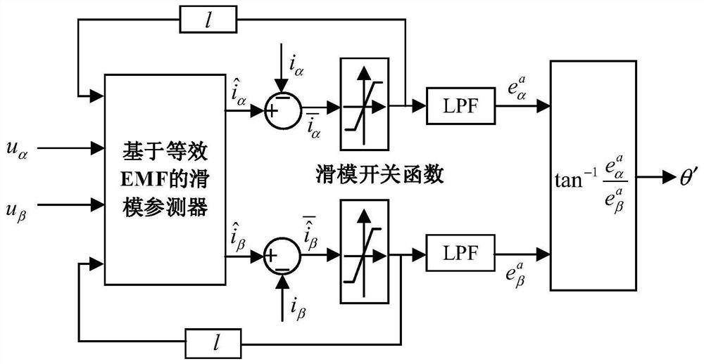
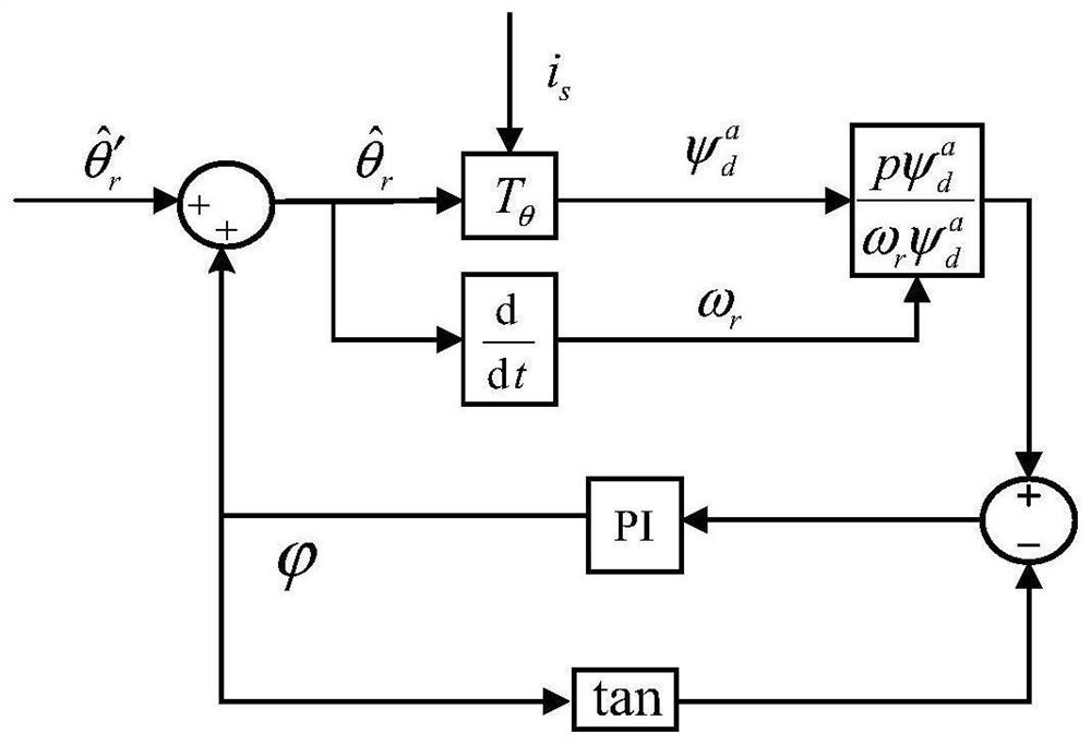
[0049] see Figure 1-2 , a novel position observation method of permanent magnet synchronous motor with dynamic error compensation, comprising the following steps:

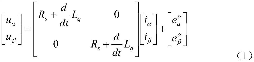
[0050] S1. In the α-β static reference frame, based on the equivalent EMF model, establish the stator voltage and current model of the embedded permanent magnet synchronous motor (IPMSM), specifically:

[0051]

[0052] In the formula, are the equivalent EMFs, u α , u β is the stator voltage; i α , i β is the stator current in the α-β stationary reference frame; R s is the stator resistance; L q is the q-axis inductance;

[0053] S2, ignoring the dynamic characteristics of the d-axis stator current, then Therefore, the formula (1) mentioned in S1 can be simplified as

[0054]

[0055] According to formula (2), the α and β components of the equivalent EMF model are the rotor position θ, respectively r ' of the sine and cosine functions, where θ' r can be obtained from the tan...


PUM


Abstract

The invention discloses a novel permanent magnet synchronous motor position observation method with a dynamic error compensation function, belonging to the technical field of self-sensing observation of the positions of synchronous motors. The novel permanent magnet synchronous motor position observation method with the dynamic error compensation function uses a sliding mode observer to estimate an equivalent electromotive force and extract a rotor position. A dynamic error compensator is adopted to suppress rotor position estimation errors caused by direct-axis current changes of the stator, and the position estimation performance of a sensorless direct torque control system of a salient pole permanent magnet synchronous motor is improved. Compared with an observer without the dynamic error compensator, an observer provided by the invention has the following advantages: (1) position observation precision in a fast torque response state, a rotating speed state and a load transient state is greatly improved; and (2) for direct torque control of high-harmonic current, the position observation precision in a stable rotating speed state is greatly improved by reducing observation errors caused by current harmonics.

Description

technical field [0001] The invention relates to the technical field of self-sensing observation of a synchronous motor position, in particular to a novel position observation method of a permanent magnet synchronous motor with dynamic error compensation. Background technique [0002] The permanent magnet synchronous motor has the advantages of simple structure, small size, low loss and high efficiency. It is widely used in industrial production, national defense, daily life and other fields. In the control system of the permanent magnet synchronous motor, it is essential to install a speed sensor or a position sensor on the motor shaft, which brings the following problems: (1) The sensor is affected by temperature, humidity, detection distance, vibration and other working conditions Influence, especially in some applications with high sensor detection accuracy, limits the application of PMSM speed control system in these special fields; (2) The sensor increases the size of ...

Claims


Application Information

Patent Timeline
IPC IPC(8): H02P21/13H02P21/00H02P21/18H02P21/30
CPCH02P21/13H02P21/0007H02P21/18H02P21/30H02P2203/03
Inventor 范平清张琳郭辉马西沛牛晓威
Owner SHANGHAI UNIV OF ENG SCI
Why Eureka
Try Eureka