Back linkage mechanism for sofa
A linkage mechanism and back technology, applied in the field of foldable back mechanism, can solve problems such as bloated sofa
- Summary
- Abstract
- Description
- Claims
- Application Information
AI Technical Summary
Problems solved by technology
Method used
Image
Examples
Embodiment 1
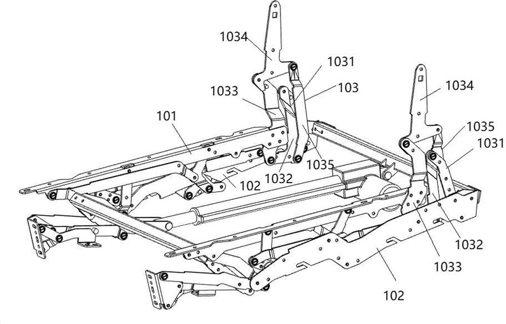
[0028] Such as figure 1 As shown, a back mechanism for a deformable sofa, the deformable sofa at least includes a seat frame 101, a suspension translation mechanism 102 and a back mechanism 103; Mutual rotatably connected link assemblies, at least one link in the link assembly is rotatably connected to the suspension translation mechanism 102; thus, when the suspension translation mechanism 102 undergoes a posture transition, the back mechanism also makes a corresponding posture transition The connecting rod assembly that constitutes the back mechanism 102 includes several rod bodies that are rotatably connected to each other from head to tail, and one is arranged on one of the rod bodies and is rotatably connected with the other connecting rod through another auxiliary connecting rod, so as to be fixed The backrest mounting seat 1034 above the rod body; the rod body connected head to tail is in a stacked folded state when the deformable sofa is in a sitting position, and when...
Embodiment 2
[0030] Embodiment 2 is a specific method based on Embodiment 1.
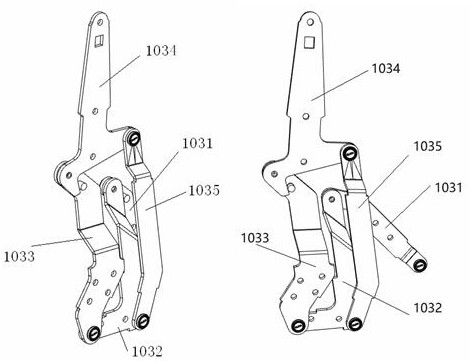
[0031] Such as figure 2 As shown, the aforementioned back mechanism for the deformable sofa, such as figure 2 As shown, the connecting rod assembly constituting the back mechanism 103 includes a first connecting rod 1031 that is rotationally connected to the suspension translation mechanism 102 at one end and transmits thrust or pulling force to the subsequent adjacent connecting rods, and the other end of the first connecting rod 1031 is connected to a One end of the middle connecting rod 1032 is connected, the other end of the middle connecting rod 1032 is rotationally connected with one end of the second connecting rod 1033, and the other end of the second connecting rod 1033 is connected with one end of the backrest mount 1034, and the backrest is installed The other end of seat 1034 is rotatably connected to an auxiliary link 1035, and the other end of this auxiliary link 1035 is rotatably connected to t...
Embodiment 3
[0033] Embodiment 3 is another specific manner based on Embodiment 2.
[0034] Such as figure 2 As shown, the aforementioned back mechanism for a movable seat or a deformable sofa realizes the purpose of controlling the action sequence of the backrest mounting seat 1034 in the link assembly by adjusting the straightness of the middle link 1032; specifically, the middle link The rod 1032 is bent in an "L" shape, and the middle connecting rod 1032, the second connecting rod 1033, and the backrest mount 1034 form a connection structure of a rectangular projection plane, wherein the auxiliary connecting rod 1035 and the middle connecting rod The connection point of 1032, that is, the pivot point, and the connection point between the second link 1033 and the intermediate link 1032, that is, the center point of the pivot point, are on the same axis, and the second link 1033, the auxiliary link 1035 and the second link 1033 and the two turning points of the intermediate link 1032 a...
PUM
 Abstract
Description
Claims
Application Information
 - R&D
- Intellectual Property
- Life Sciences
- Materials
- Tech Scout
- Unparalleled Data Quality
- Higher Quality Content
- 60% Fewer Hallucinations
Browse by: Latest US Patents, China's latest patents, Technical Efficacy Thesaurus, Application Domain, Technology Topic, Popular Technical Reports.
© 2025 PatSnap. All rights reserved.Legal|Privacy policy|Modern Slavery Act Transparency Statement|Sitemap|About US| Contact US: help@patsnap.com


