Hemostasis compressor for department of cardiology

A compressor and cardiology technology, applied in the field of medical equipment, can solve the problems of inconvenient movement, inconvenient cleaning and disinfection of pressure plates, and increase the risk of cross-infection of patients, so as to achieve simple structure, easy cleaning and disinfection, and reduce cross-infection of patients The effect of the risk

Pending Publication Date: 2021-06-29
郑曼
View PDF9 Cites 1 Cited by
  • Summary
  • Abstract
  • Description
  • Claims
  • Application Information

AI Technical Summary

Problems solved by technology

[0004] The purpose of the present invention is to solve the problem that most of the hemostatic compressors in the prior art are fixed during use and are inconvenient to move, and it is not convenient to clean and disinfect the pressure plate after use, thus increasing the risk of cross-infection of patients. risk disadvantages while presenting a hemostatic compressor for cardiology

Method used


Image

  • Hemostasis compressor for department of cardiology
  • Hemostasis compressor for department of cardiology
  • Hemostasis compressor for department of cardiology

Examples


Embodiment 1

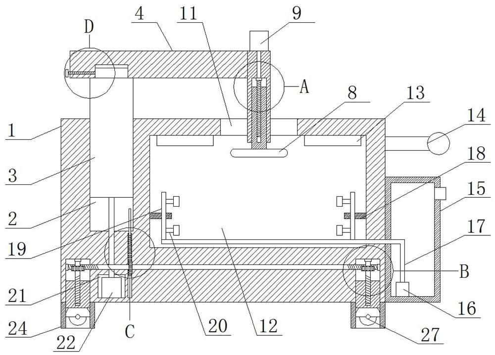
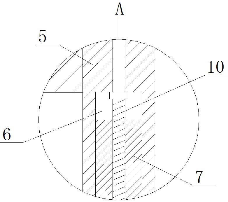
[0027] refer to Figure 1-5 , a hemostatic compressor for cardiology, comprising a housing 1, a first chute 2 is provided on the top of the housing 1, a support column 3 is slidably installed in the first chute 2, and a horizontal cross is installed on the top of the support column 3 for rotation. One side of the rod 4 and the cross bar 4 is fixedly installed with a fixed rod 5, the top of the fixed rod 5 is fixedly mounted with a motor 9, and the bottom of the fixed rod 5 is provided with a second chute 6, and a hemostatic mechanism is arranged in the second chute 6 There is a cleaning chamber 12 inside the housing 1, and two symmetrical drying lamps 13 are fixedly installed on the inner wall of the top of the cleaning chamber 12, and a placement opening 11 is opened on the top of the housing 1, and the placement opening 11 communicates with the cleaning chamber 12. A push handle 14 is fixedly installed on one side of the body 1, a water tank 15 is fixedly installed on one si...

Embodiment 2

[0036] refer to Figure 1-5 , a hemostatic compressor for cardiology, comprising a housing 1, a first chute 2 is provided on the top of the housing 1, a support column 3 is slidably installed in the first chute 2, and a horizontal cross is installed on the top of the support column 3 for rotation. Rod 4, one side of cross bar 4 is fixedly installed with fixed rod 5 by welding, and the top of fixed rod 5 is fixedly installed with motor 9 by welding, and the bottom of fixed rod 5 is provided with second chute 6, and in the second chute 6 A hemostatic mechanism is provided, and a cleaning chamber 12 is opened in the housing 1, and two symmetrical drying lamps 13 are fixedly installed on the top inner wall of the cleaning chamber 12 by welding. The top of the housing 1 is provided with a placement port 11, which is connected with the The cleaning chamber 12 communicates, one side of the housing 1 is fixedly installed with a push handle 14 through welding, one side of the housing 1...


PUM


Abstract

The invention belongs to the field of medical equipment, particularly relates to a hemostasis compressor for the department of cardiology, and aims to solve the problem that the risk of cross infection of patients is increased due to the fact that most of existing hemostasis compressors are fixed and inconvenient to move in the using process, and a pressing plate is inconvenient to clean and disinfect after being used. According to the present scheme, the hemostasis compressor comprises a shell, wherein a first sliding groove is formed in the top of the shell, a supporting column is installed in the first sliding groove in a sliding mode, a cross rod is rotationally installed at the top of the supporting column, a fixing rod is fixedly installed on one side of the cross rod, a motor is fixedly installed at the top of the fixing rod, a second sliding groove is formed in the bottom of the fixing rod, a hemostasis mechanism is arranged in the second sliding groove, and a cleaning cavity is formed in the shell. According to the hemostasis compressor for the department of cardiology, the hemostasis compressor can be conveniently stored and moved in the using process, the pressing plate can be conveniently cleaned and disinfected after the hemostasis compressor is used, and therefore, the risk of cross infection of patients can be reduced, and the hemostasis compressor is simple in structure and convenient to use.

Description

technical field [0001] The invention relates to the technical field of medical equipment, in particular to a hemostatic compressor for cardiology. Background technique [0002] Compression hemostat uses mechanical compression force to promote wound coagulation and preliminary closure, which requires a certain compression time. Clinical catheter intervention in the Department of Cardiology refers to placing a catheter through the femoral artery into the patient's heart or related blood vessels for treatment. During the operation, the catheter needs to be punctured through the femoral artery. After the operation, the puncture catheter and sheath of the femoral artery When the tube is to be removed from the artery, it is necessary to use a compression hemostatic device to press the puncture site accurately for a long time to achieve the purpose of rapid hemostasis. [0003] However, most of the existing hemostatic compressors are fixed during use, which is not easy to move, an...

Claims


Application Information

Patent Timeline
Patent Type & Authority Applications(China)
IPC IPC(8): A61B17/12A61L2/18
CPCA61B17/12A61L2/18A61B2017/12004A61L2202/24A61L2202/17
Inventor 郑曼
Owner 郑曼
Why Eureka
Try Eureka