Waste gas treatment device for 3D printing

An exhaust gas treatment device and 3D printing technology, applied in the field of 3D printing, can solve problems such as air purification, environmental pollution, and environmental pollution, and achieve the effects of meeting practical needs, reducing environmental pollution, and improving utilization

Inactive Publication Date: 2021-06-29
WUHU INST OF TECH
View PDF0 Cites 0 Cited by
  • Summary
  • Abstract
  • Description
  • Claims
  • Application Information

AI Technical Summary

Problems solved by technology

[0002] 3D printing is usually realized by using digital technology material printers. It is often used to manufacture models in mold manufacturing, industrial design and other fields, and is gradually used in the direct manufacturing of some products. There are already parts printed using this technology. , the technology has applications in jewelry, footwear, industrial design, architecture, engineering and construction, automotive, aerospace, dental and medical industries, education, geographic information systems, civil engineering, firearms, and other fields where plastics can be bonded In the process of melting materials, harmful gases will be formed, and the discharge of these gases will pollute the surrounding environment. The air filter device of the current 3D printer, in the process of filtering harmful gases, the purification effect of harmful gases is not thorough. As a result, the discharged gas still contains harmful substances, which still pollute the surrounding environment, and the activated carbon adsorption particles cannot be fully used, which reduces the utilization rate and cannot effectively purify the air, which cannot meet the use requirements

Method used


Image

  • Waste gas treatment device for 3D printing
  • Waste gas treatment device for 3D printing
  • Waste gas treatment device for 3D printing

Examples


Embodiment Construction

[0017] Below in conjunction with accompanying drawing and specific embodiment the present invention is described in further detail:

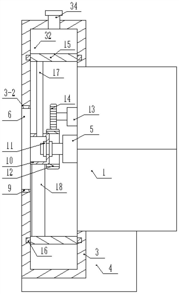
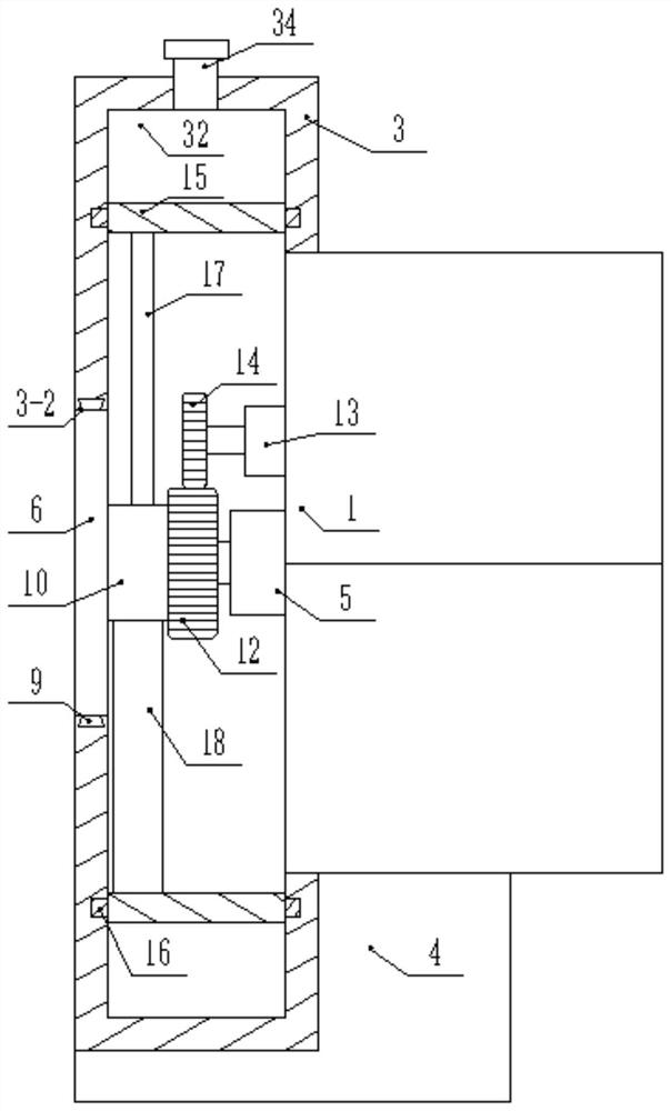
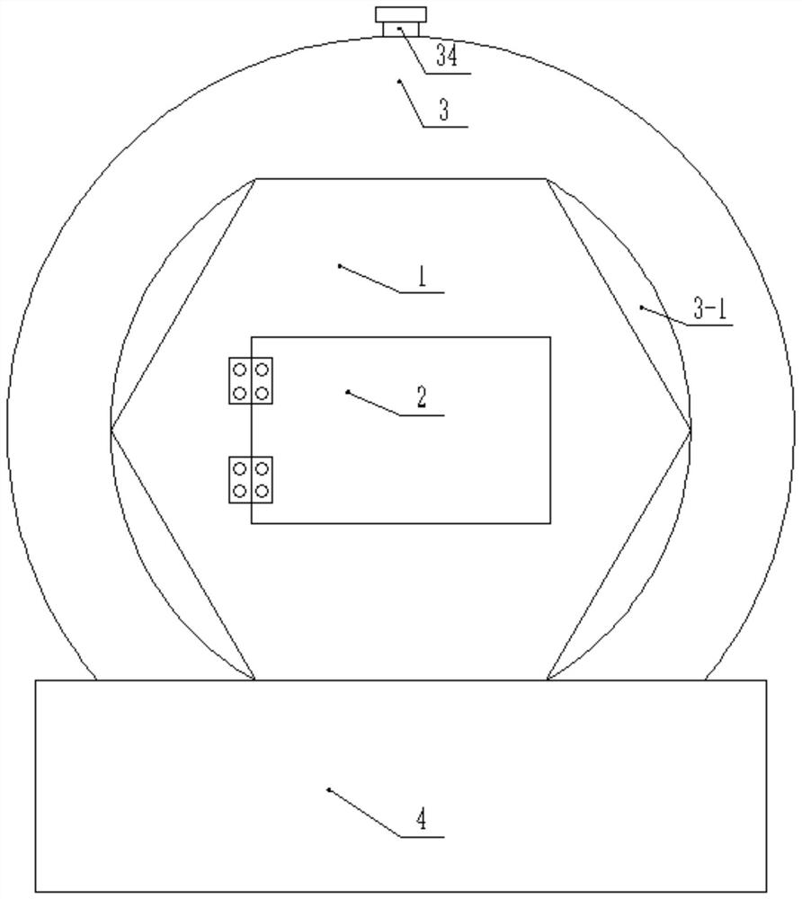
[0018] like figure 1 , figure 2 , image 3 , Figure 4 , Figure 5 , Image 6As shown, a waste gas treatment device for 3D printing includes a 3D printer body 1, the 3D printer body 1 is electrically connected to an external controller, the side wall of the 3D printer body 1 is hinged with an organic door 2 through a hinge, the One side of the 3D printer body 1 is provided with a first barrel body 3, the section of the first barrel body 3 is circular, the bottom surface of the first barrel body 3 is fixedly connected with a base 4, and the top surface of the base 4 is connected to the 3D printer body 1. The bottom surface is fixedly connected. The side wall of the first barrel body 3 has a first through hole 3-1. One end of the 3D printer body 1 is set in the first through hole 3-1. The 3D printer body 1 and the first through hole 3-1 A b...


PUM

PropertyMeasurementUnit
Wall thicknessaaaaaaaaaa

Abstract

The invention discloses a waste gas treatment device for 3D printing, wherein the waste gas treatment device for 3D printing comprises a 3D printer body; a motor is fixedly connected to the side wall of the 3D printer body; the motor is electrically connected with an external controller; a first spring is a compression spring; two transverse plates are symmetrically and fixedly connected to the inner wall of a first barrel body; first sealing strips are fixedly embedded into the side walls of the transverse plates through glue; a three-way pipe is fixedly embedded in a vertical plate, two end openings of the three-way pipe are arranged on the two sides of the vertical plate respectively and communicated with the first barrel body, the top end of the three-way pipe penetrates out of the first barrel body and is in threaded connection with a cover body, the wall thickness of a circular ring is 8 mm-10 mm, the disc is made of aluminum alloy materials, and the model of the motor is BWY27-23-7.5; and the heat dissipation of printing equipment can be assisted while waste gas is fully purified, so that the environment is indirectly protected, the environmental pollution is reduced, the rolling of activated carbon particles can be realized, the activated carbon is fully utilized while the waste gas is fully purified, the utilization rate is increased, and the practical requirements are met.

Description

technical field [0001] The invention relates to the technical field of 3D printing, in particular to a high-efficiency waste gas treatment device for 3D printing. Background technique [0002] 3D printing is usually realized by using digital technology material printers. It is often used to manufacture models in mold manufacturing, industrial design and other fields, and is gradually used in the direct manufacturing of some products. There are already parts printed using this technology. , the technology has applications in jewelry, footwear, industrial design, architecture, engineering and construction, automotive, aerospace, dental and medical industries, education, geographic information systems, civil engineering, firearms, and other fields where plastics can be bonded In the process of melting materials, harmful gases will be formed, and the discharge of these gases will pollute the surrounding environment. The air filter device of the current 3D printer, in the process...

Claims


Application Information

Patent Timeline
IPC IPC(8): B01D46/00
CPCB01D46/0045B01D46/62
Inventor 徐光晨许佳潘友勇
Owner WUHU INST OF TECH
Why Eureka
Try Eureka