Supercharge Your Innovation With Domain-Expert AI Agents!

Heat exchanger for air conditioner

A technology for air conditioners and heat exchangers, which is used in heat exchange equipment, air conditioning systems, space heating and ventilation, etc., and can solve the problems of increased heat transfer effect, reduced heat transfer performance, and increased heat transfer performance.

Inactive Publication Date: 2003-12-10
SAMSUNG ELECTRONICS CO LTD
View PDF7 Cites 0 Cited by
  • Summary
  • Abstract
  • Description
  • Claims
  • Application Information

AI Technical Summary

Problems solved by technology

[0008] However, if the conventional heat exchanger with the above-mentioned structure is adopted, due to the turbulent flow of the heat exchange fluid on the flat fin 1, in particular, a plurality of slots can be provided on the flat fin 1 to reduce the thickness of the boundary layer. 5a, 5b, 5c, 5d, 5e, 5f, because they can form thin temperature boundary layers, compared with the flat heat sink 1 without slots, the heat transfer performance is increased; however, if the local heat transfer performance is compared, At the slots 5a, 5b on the flow-stopping side of the flat heat sink 1, a thinner temperature boundary layer is formed, and the heat transfer performance is also high; while at the slots 5c, 5d, 5e, 5f on the downstream side , due to entering the temperature boundary layer formed in the aforementioned upstream side slit portions 5a, 5b, the heat transfer performance is reduced, and at the same time, a dead flow area where the air does not flow is generated behind the heat transfer tube 2; in addition, because each plate The air flowing between the cooling fins does not mix, but flows in parallel, so it is impossible to expect an increase in the heat transfer effect due to the mixing of air

Method used


Image

  • Heat exchanger for air conditioner
  • Heat exchanger for air conditioner
  • Heat exchanger for air conditioner

Examples


Embodiment Construction

[0014] Next, an embodiment of the heat exchanger for an air conditioner of the present invention will be described in detail with reference to the accompanying drawings.

[0015] In the drawings, the same names and symbols are given to the same components as the conventional ones, and detailed description is omitted.

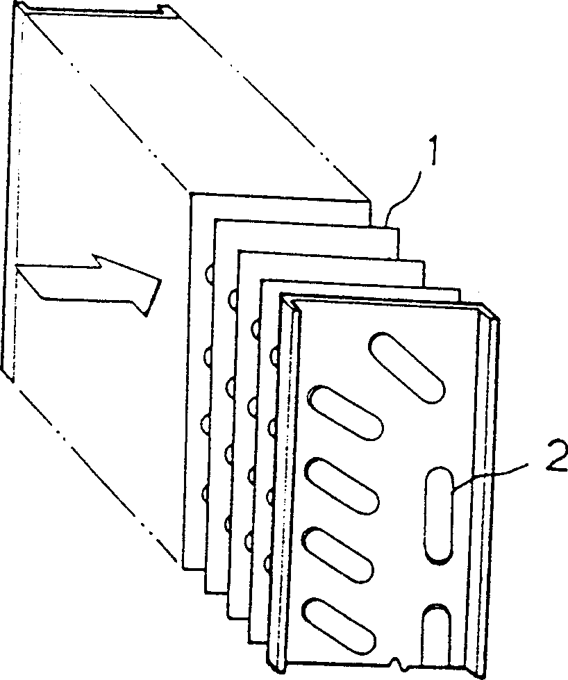
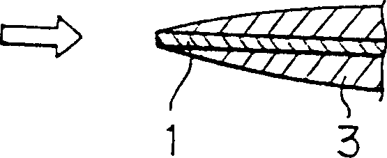
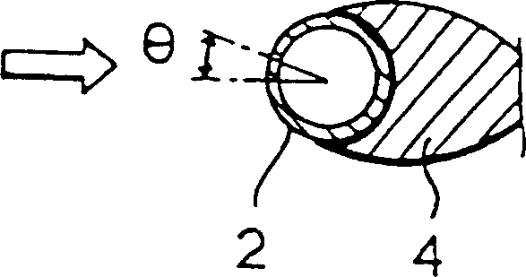
[0016] The heat exchanger of the air conditioner of an embodiment of the present invention is made up of the following parts as shown in Figure 6: air flows therebetween, mutually becomes predetermined space, a plurality of flat fins 1 of parallel arrangement; The flat heat sink 1 is staggered up and down and inserted into the configuration at right angles, and there are heat transfer tubes 2 for fluid flow inside; A plurality of first slot-type louver groups 20a, 20b respectively arranged on the back side and the surface of the flat fin 1 on the front side of the heat transfer tube 2; The turbulent airflow diffused by the slot-type louver groups 20a, 20b cause...


PUM


Abstract

To improve the heat transmission capability of a heat exchanger of an air-conditioner, on the heat exchanger composed of tablet heat-dissipating plates arranged in parallel at fixed interval and heat transmission pipes vertically inserted into the tablet heat-dissipating plates, the following parts are sequentially arranged on the surfaces and the backs of the tablet heat-dissipating plates: a first group of slotted louver board groups causing turbulent flow when the air passes through the front of the heat transmission pipes; a second group of slotted louver board groups causing turbulent flow when air passes through the front of the upper and the lower sides of the heat transmission pipes; a third group of slotted louver board groups causing turbulent flow when the turbulent air spread by the second group passes through the center of the upper and the lower sides of the heat transmission pipes; a fourth group of slotted louver board groups causing turbulent flow when the air spread by the third group passes through the back of the upper and the lower sides of the heat transmission pipes; and a fifth group of slotted louver board groups causing turbulent flow when the air spread by the fourth group passes through the back of the upper and the lower sides of the heat transmission pipes and can effectively reduce the dead flow zones in the back of the heat transmission pipes.

Description

technical field [0001] The present invention relates to a heat exchanger for an air conditioner, in particular to a heat exchanger for an air conditioner in which a plurality of slot-type louver groups are arranged between each of a plurality of heat transfer tubes on a flat fin. Background technique [0002] Generally, heat exchangers used on existing air conditioners, such as figure 1 As shown, it is composed of a plurality of flat fins 1 arranged in parallel at predetermined intervals and a plurality of heat transfer tubes 2 arranged orthogonally to the flat fins 1 and alternately arranged. [0003] Furthermore, the air is between the aforementioned plurality of flat heat sinks 1, along the figure 1 The flow in the direction of the white arrow in the middle exchanges heat with the fluid in the heat transfer tube 2 . [0004] In addition, the thermal fluid characteristics around the aforementioned flat heat sink 1, such as figure 2 As shown, the thickness of the temper...

Claims


Application Information

Patent Timeline
IPC IPC(8): F24F1/00F28F1/32
CPCF28F1/325Y10S165/502
Inventor 尹柏金永生
Owner SAMSUNG ELECTRONICS CO LTD
Features
  • R&D
  • Intellectual Property
  • Life Sciences
  • Materials
  • Tech Scout
  • Unparalleled Data Quality
  • Higher Quality Content
  • 60% Fewer Hallucinations
Learn More