An air flotation device for optical device coupling and using method

An optical device and air flotation technology, which is applied in auxiliary devices, laser welding equipment, auxiliary welding equipment, etc., can solve the problems of relative position change and affecting the performance of optical devices, so as to avoid the existence of angle and ensure the effect of performance

Active Publication Date: 2022-07-05
深圳市亚微科技有限公司
View PDF5 Cites 0 Cited by
  • Summary
  • Abstract
  • Description
  • Claims
  • Application Information

AI Technical Summary

Problems solved by technology

[0005] For the coupling welding equipment existing in the prior art, the mechanical method is generally used for flattening. It is difficult for the mechanical flattening method to completely flatten the two surfaces, and there will always be a little angle, which will cause the relative position of the optical port and the optical device to change after welding. For the problem of affecting the performance of the optical device, the present invention provides a method that can easily flatten the bottom of the optical fiber socket and the upper part of the semi-finished optical device, avoiding the existence of angles, and the relative position of the optical port and the optical device will not change after welding , an air flotation device for optical device coupling that effectively guarantees the performance of the optical device and its use method

Method used


Image

  • An air flotation device for optical device coupling and using method
  • An air flotation device for optical device coupling and using method
  • An air flotation device for optical device coupling and using method

Examples


Embodiment 1

[0035] like Figure 1-4 As shown, an air flotation device for optical device coupling includes a support table 1, a ball seat 2, a floating ball 3, a compressed air joint 8 and a vacuum joint 9, the support table 1 is a cylindrical support table, and the support table 1 There is an installation cavity inside the ball seat 2, the ball seat 2 is a cylindrical structure, and the inner side wall of the ball seat 2 is provided with an annular groove 24, and the side wall of the ball seat 2 is symmetrically opened with a first gas path 5 and a second gas path 6. Both the first air passage 5 and the second air passage 6 communicate with the annular groove 24, the floating ball 3 is movably embedded inside the upper end of the ball seat 2, and the top of the floating ball 3 extends to the outside of the upper end of the ball seat 2 , the top of the floating ball 3 is provided with a horizontal plane, and the top of the floating ball 3 is provided with a station slot 4, the side of the...

Embodiment 2

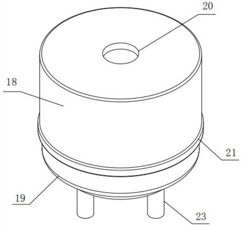
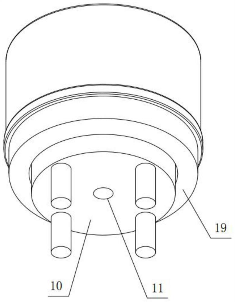
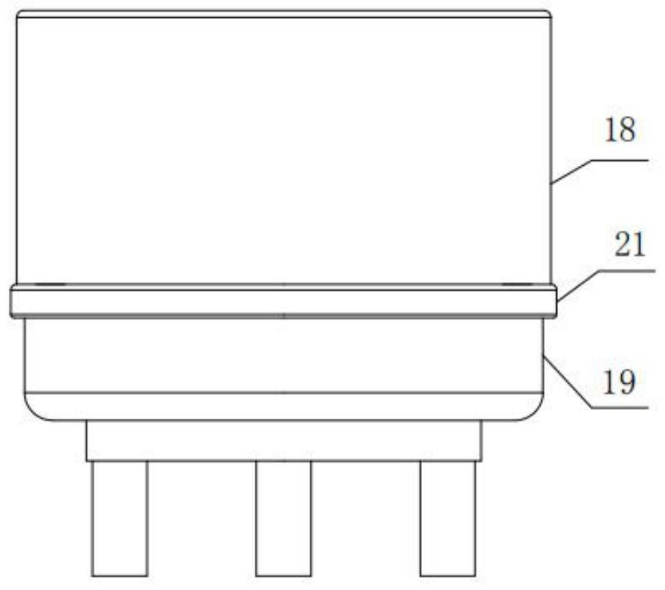
[0038] like Figure 1-7 As shown, the difference between this embodiment and Embodiment 1 is that the air flotation device used for optical device coupling also includes a dust-proof assembly, and the dust-proof assembly includes a dust-proof cover 18 and a dust-proof cloth bag 19, and the dust-proof cover 18 is fixed It is installed on the top of the floating ball 3, and the upper surface of the dust cover 18 is a horizontal plane. The center of the dust cover 18 is provided with a through hole 20 that is matched with the station slot 4, and the dust cover 18 has a direction toward the support table. 1. The side wall provided, the edge of the side wall of the dust cover 18 is integrally provided with an annular slide rail 22, the through hole 20 is completely overlapped with the station slot 4, the dust cloth bag 19 is a ring structure, and the outer ring of the dust cloth bag 19 is An annular slider 21 is fixedly installed on the edge, and an annular fitting seat 7 is fixedl...

Embodiment 3

[0044] like Figure 1-9 As shown, the difference between this embodiment and Embodiment 2 is that at least three installation grooves 13 are evenly opened on the inner side wall of the ball seat 2 (theoretically, the three installation grooves 13 are sufficient to ensure the stability of the floating ball 3). The bottoms of the mounting grooves 13 are fixedly mounted on the first spring seats 14 , the upper parts of the first spring seats 14 are fixedly mounted with springs 15 , and the upper ends of the springs 15 are fixedly mounted with the second spring seats 16 . The upper part of the 16 is rotated and embedded with a universal ball 17. The spherical surface of the universal ball 17 is in conflict with the spherical surface of the floating ball 3. The spring 15 can be used to lift the floating ball 3 to offset the gravity of the floating ball 3, so that the floating ball 3 is more stable. Easy to float. In addition, under the action of the universal ball 17 , the frictio...


PUM


Abstract

The invention discloses an air flotation device for optical device coupling, which comprises a support table, a ball seat, a floating ball, a compressed air joint and a vacuum joint. The support table is a cylindrical support table, and the inside of the support table has an installation cavity. The ball seat is a cylindrical structure, and the inner side wall of the ball seat is provided with an annular groove, and the side wall of the ball seat is symmetrically provided with a first air path and a second air path, both of which are Connected with the annular groove, the floating ball is movably embedded inside the upper end of the ball seat, and the top of the floating ball extends to the outside of the upper end of the ball seat, the top of the floating ball is provided with a horizontal plane, and the top of the floating ball is provided with a working position slot . The invention can conveniently make the bottom of the optical fiber socket and the two surfaces of the upper part of the semi-finished product of the optical device completely flat, avoid the existence of angles, the relative position of the optical port and the optical device will not change after welding, and effectively ensure the performance of the optical device.

Description

technical field [0001] The invention belongs to the technical field of optical device production, and in particular relates to an air flotation device for coupling optical devices and a method of using the same. Background technique [0002] Optical devices are divided into active devices and passive devices. Optical active devices are optoelectronic devices that require additional energy to work in optical communication systems and can convert electrical signals into optical signals or convert optical signals into electrical signals. The heart of the transmission system. Optical passive devices are optoelectronic devices that do not require external energy to drive work. [0003] The optical port of the optical device is connected. After the coupling is completed, the optical port and the welding surface of the device need to be flattened before laser welding to ensure that the relative position of the two coupling components does not change during the welding process. The...

Claims


Application Information

Patent Timeline
Patent Type & Authority Patents(China)
IPC IPC(8): B23K26/21B23K26/70B23K37/04
CPCB23K26/21B23K26/702B23K37/0426
Inventor 曾同新
Owner 深圳市亚微科技有限公司
Why Eureka
Try Eureka