
Manufacturing method of prestressed thin plate composite floor slab framework

A technology of a laminated floor and a manufacturing method, applied in the field of floor manufacturing, can solve the problems of difficulty in ensuring that square sheets are perpendicular to each other, the steel frame cannot be fully fitted, and the quality of the skeleton of the prestressed sheet laminated floor is affected.

Pending Publication Date: 2021-07-02
王亚龙
View PDF0 Cites 0 Cited by
  • Summary
  • Abstract
  • Description
  • Claims
  • Application Information

AI Technical Summary

Problems solved by technology

[0005] The present invention provides a method for making a prestressed thin-slab laminated floor skeleton, aiming to solve the following problems in the process of manufacturing the prestressed thin-slab laminated floor skeleton: when cutting the four corners of a square thin slab, the existing It is difficult for the cutting equipment to ensure that each corner of the square thin plate is cut with the same length of the cutting edge, and it is difficult to ensure that the cut edges of each corner of the square thin plate are perpendicular to each other, resulting in the edge of the thin plate and the steel frame being aligned. The frame cannot be fully fitted, resulting in gaps in the prestressed thin-slab laminated floor skeleton, which affects the quality of the prestressed thin-slab laminated floor skeleton

Method used


Image

  • Manufacturing method of prestressed thin plate composite floor slab framework
  • Manufacturing method of prestressed thin plate composite floor slab framework
  • Manufacturing method of prestressed thin plate composite floor slab framework

Examples


Embodiment Construction

[0038] The embodiments of the present invention will be described in detail below with reference to the accompanying drawings, but the present invention can be implemented in many different ways defined and covered by the claims.

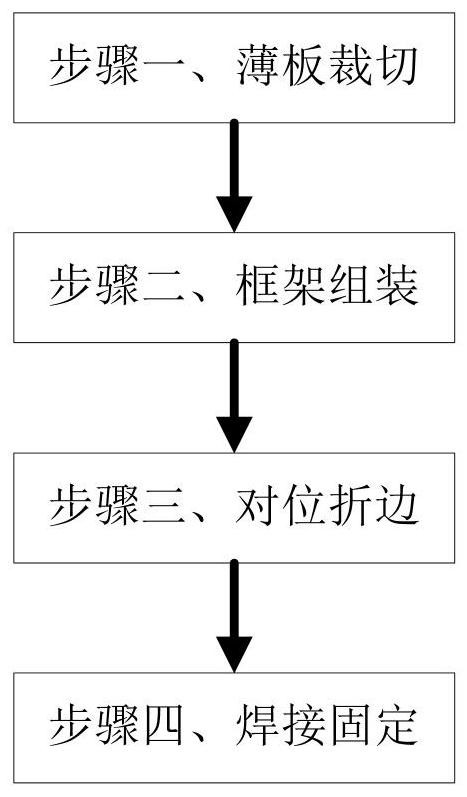
[0039] Such as figure 1 As shown, this embodiment provides a method for manufacturing a prestressed thin plate laminated floor skeleton, including the following steps:

[0040] Step 1, sheet cutting: cutting the metal sheet to obtain a cross-shaped sheet.

[0041] Step 2, frame assembly: the ends of the steel bars are fixedly connected together to obtain a steel bar frame.

[0042] Step 3. Alignment folding: Align the cross-shaped thin plate with the steel frame, and fold the cross-shaped thin plate.

[0043] Step 4. Welding and fixing: Weld the cross-shaped thin plate and the steel frame together to obtain the laminated floor skeleton of the prestressed thin plate.

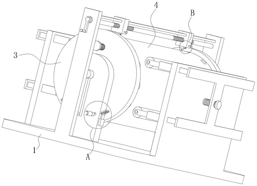
[0044] Wherein, step 1 adopts such as Figure 2 to Figure 8 A kind of prestres...


PUM


Abstract

The invention belongs to the technical field of floor slab manufacturing, and particularly relates to a manufacturing method of a prestressed thin plate composite floor slab framework. The method comprises the following steps of step 1, thin plate cutting, cutting a metal thin plate to obtain a cross-shaped thin plate; step 2, frame assembling is conducted, the ends of the steel bars are fixedly connected together, and a steel bar frame is obtained; step 3, aligning and folding edges, aligning the cross-shaped thin plate and the steel bar frame together, and folding the edges of the cross-shaped thin plate; step 4, welding and fixing are conducted, the cross-shaped thin plate and the steel bar frame are welded together to obtain the prestressed thin plate composite floor slab framework; and in the first step, the prestressed thin plate composite floor slab framework manufacturing device is adopted for cooperation. According to the square thin plate cutting device, the lengths of the cutting edges of all corners of a square thin plate after cutting are equal is guaranteed, and meanwhile the cutting edges of all the corners of the square thin plate after cutting are perpendicular to one another is guaranteed.

Description

technical field [0001] The invention belongs to the technical field of floor slab manufacturing, and in particular relates to a method for manufacturing a prestressed thin plate laminated floor slab skeleton. Background technique [0002] Prestressed thin-slab laminated floor is a better structural form combining prefabricated and cast-in-place concrete. The prefabricated prestressed slabs are combined with the upper cast-in-place concrete layer as a whole and work together. The prestressed main reinforcement of the thin slab is the main reinforcement of the laminated floor, and the upper concrete cast-in-place layer is only equipped with negative moment reinforcement and structural reinforcement. The prestressed thin-slab laminated floor is used as the bottom form of the cast-in-place concrete layer, and it is not necessary to support the formwork for the cast-in-place layer. The bottom surface of the thin board is smooth and flat, and the ceiling can no longer be plaster...

Claims


Application Information

Patent Timeline
IPC IPC(8): B23P15/00E04B5/38
CPCB23P15/00E04B5/38
Inventor 王亚龙
Owner 王亚龙
Learn More