Driving device for flexible joint of minimally invasive surgical instrument based on universal ball joint control

A technology of spherical universal joints and flexible joints, which can be used in surgery, medical science, etc., and can solve problems such as difficulty in driving flexible joints, complex structures, and bloated overall design

Pending Publication Date: 2021-12-14
江苏木偶医疗器械有限公司
View PDF2 Cites 0 Cited by
  • Summary
  • Abstract
  • Description
  • Claims
  • Application Information

AI Technical Summary

Problems solved by technology

[0002] At present, flexible joints have been widely used in minimally invasive surgical instruments, but how to flexibly drive flexible joints has always been a difficult point
[0003] Most companies use the disc cable to drive the flexible joint, and through the overall rotation, the universal direction of the flexible joint is realized. This method limits the flexibility of the flexible joint movement and makes the performance of the flexible joint movement unintuitive.
[0004] In the prior art, there is also a structure that can directly drive the movement of the flexible four directions, but the corresponding structure is relatively complicated, and there are also requirements for the installation position of the structure, and when the flexible joint is driven by soft lock to realize the movement, each There are also requirements for the consistency of the pulling force of the root soft locks and the forward and backward movement distance of the two corresponding soft locks. It is difficult to guarantee during the installation process. In the prior art, the motor is used to achieve precise control, but this limits the design of the back-end structure. Makes the overall design very bloated and not lightweight
[0005] And there is a problem of entanglement in the soft lock during use, which increases the difficulty of design
Due to its soft-lock driving characteristics, the existing flexible joint motion will also drive it to support the outer tube, resulting in deformation of the outer tube and affecting the operation

Method used


Image

  • Driving device for flexible joint of minimally invasive surgical instrument based on universal ball joint control
  • Driving device for flexible joint of minimally invasive surgical instrument based on universal ball joint control
  • Driving device for flexible joint of minimally invasive surgical instrument based on universal ball joint control

Examples


Embodiment 1

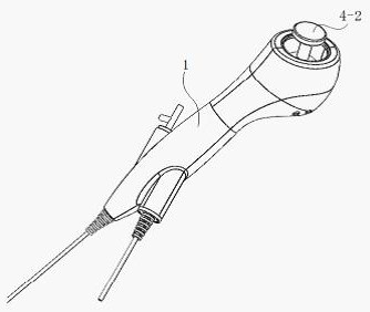
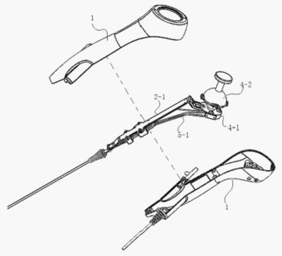
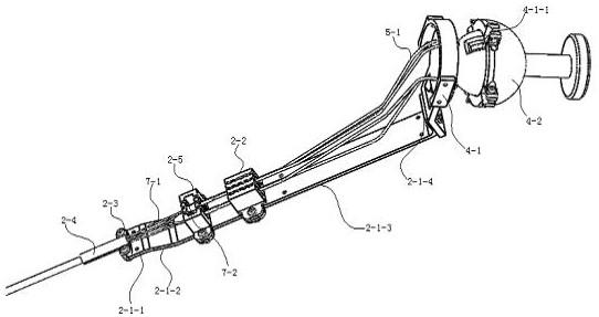
[0054] A driving device for a flexible joint of a minimally invasive surgical instrument controlled by a spherical universal joint, comprising an operating handle housing 1 and a flexible joint 2; also including a soft lock 3, a buffer assembly, a rear-end control mechanism and a support set in the housing Frame 2-1, support frame 2-1 is fixedly provided with outer tube fixing part 2-3 and limit seat 2-2, outer tube fixing part 2-3 is fixedly provided with outer tube 2-4, one end of flexible joint 2 It is fixed in the outer tube 2-4; the limit seat 2-2 is provided with a limit groove; the rear-end control mechanism is a spherical universal joint, and the spherical universal joint includes the rear-end first-level component 4-1 and a rear-end one The rear-end secondary assembly 4-2 concentrically arranged by the first-stage assembly 4-1, the rear-end primary assembly 4-1 is provided with a rotating inner spherical surface, the rear-end secondary assembly 4-2 is provided with a r...

Embodiment 2

[0064] The rest are consistent with the scheme of embodiment 1, and the limiting protrusion 4-2-1 is a cylindrical protrusion. The limit protrusion 4-2-1 is a cylindrical protrusion, and the limit protrusion is arranged at the symmetrical position of the inner sphere center of the rear-end secondary component 4-2. When the rear-end secondary component 4-2 moves to the X direction , the limit projection slides in the notch of the rear-end primary assembly 4-1, and when the rear-end secondary assembly 4-2 moves in the Y direction, the limit projection slides in the rear-end primary assembly 4-1. 1 in the notch to perform rotational movement, when the rear-end secondary component 4-2 rotates coaxially, since the limiting protrusion is in the notch of the rear-end primary component 4-1, it is limited by the notch, so the rear The first-stage assembly 4-1 at the end and the second-stage assembly 4-2 at the rear end cannot perform head-circumferential movement with each other.

Embodiment 3

[0066] The rest are consistent with the scheme of embodiment 1 or 2, the present invention also includes an adjustment assembly, the adjustment assembly includes a screw 6-1 and a nut 6-2 compatible with the screw 6-1, and the rear end secondary assembly 4-2 is evenly The limited lifting lug 4-2-2 is distributed, the screw 6-1 forms a detachable fixed connection with the limiting lifting lug 4-2-2 through the nut 6-2, and the screw 6-1 is provided with a positioning hole 6-1- 1. One end of the flexible lock 3 is adapted to connect with the flexible joint 2, and the other end first passes through the spring protection tube 5-1 or the guide hose, then passes through the positioning hole 6-1-1 and is fixed to the screw 6- of the adjustment component 1, the number of buffer components: the number of positioning channels 4-1-1: the number of limit lifting lugs 4-2-2: the number of screws 6-1: the number of soft locks 3=1:1:1:1 :1.

[0067] The adjustment component is used to preci...


PUM


Abstract

The invention discloses a driving device for a flexible joint of a minimally invasive surgical instrument based on universal ball joint control, which comprises an operating handle shell, the flexible joint, a flexible lock, a buffer assembly, a rear end control mechanism and a support frame arranged in the shell, and one end of the flexible joint is fixed in an outer tube; the rear end control mechanism comprises a rear-end first-stage assembly and a rear-end second-stage assembly concentric with the rear-end first-stage assembly. The rear-end first-stage assembly and the rear-end second-stage assembly conduct relative circumferential movement through cooperation of a rotary inner spherical surface and a rotary outer spherical surface; and one end of the flexible lock is connected with the flexible joint in a matched mode, and the other end of the flexible lock is in linkage fit with the buffering assembly and the rear end control mechanism. Workers can conveniently install the flexible joint, the cost is reduced, and meanwhile different application conditions of the flexible joint can be met through the flexible lock driving mode.

Description

technical field [0001] The invention relates to the technical field of medical electronic equipment, in particular to a flexible joint driving method applied to minimally invasive surgical endoscope products. Background technique [0002] At present, flexible joints have been widely used in minimally invasive surgical instruments, but how to flexibly drive flexible joints has always been a difficult point. [0003] Most companies use the disc cable to drive the flexible joint, and through the overall rotation, the universal direction of the flexible joint is realized. This method limits the flexibility of the flexible joint movement and makes the performance of the flexible joint movement unintuitive. [0004] In the prior art, there is also a structure that can directly drive the movement of the flexible four directions, but the corresponding structure is relatively complicated, and there are also requirements for the installation position of the structure, and when the fle...

Claims


Application Information

Patent Timeline
IPC IPC(8): A61B17/00
CPCA61B17/00234A61B2017/00367A61B2017/00398
Inventor 李晓贞徐欣良宜王屹初朱鸿
Owner 江苏木偶医疗器械有限公司
Why Eureka
Try Eureka