A kind of diversion type wind boosting equipment for ships

A wind power and propulsion technology, which is applied in ship propulsion, wind propulsion components, ship construction, etc., can solve the problems of ship stability and course keeping ability, great impact on ship safety, and large ship impact, etc., and achieve compact structure , easy operation and high utilization rate

Active Publication Date: 2022-05-17
CHINA SHIP SCIENTIFIC RESEARCH CENTER (THE 702 INSTITUTE OF CHINA SHIPBUILDING INDUSTRY CORPORATION)
View PDF0 Cites 0 Cited by
  • Summary
  • Abstract
  • Description
  • Claims
  • Application Information

AI Technical Summary

Problems solved by technology

[0003] Among the existing wind energy utilization equipment, sails have remarkable energy-saving effects. Steel wing sails can adapt to different wind directions by adjusting the angle of attack and improve the utilization rate of wind energy. The impact is greater; wing sails can be applied to many wind directions, but their structural strength is low and their weight is high; kites are often used on small yachts, and when the wind direction is suitable, they can produce a great boosting effect, but the applicable wind direction is small The safety of the ship is greatly affected; the marine booster rotor can be applied to a wide range of wind directions and has a good effect, and has relatively little impact on the ship, but it requires a high speed and needs to provide additional driving force. The stability requirements of the mechanism are relatively high, which puts forward high requirements for construction and processing
In addition, these existing devices will inevitably produce component forces along the ship’s width direction while boosting, and the more obvious the boosting effect is, the greater the component force will be. is unfavorable

Method used


Image

  • A kind of diversion type wind boosting equipment for ships
  • A kind of diversion type wind boosting equipment for ships
  • A kind of diversion type wind boosting equipment for ships

Examples


Embodiment Construction

[0031] The specific implementation manner of the present invention will be described below in conjunction with the accompanying drawings.

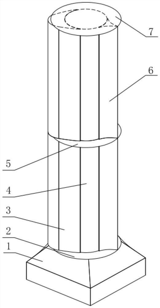
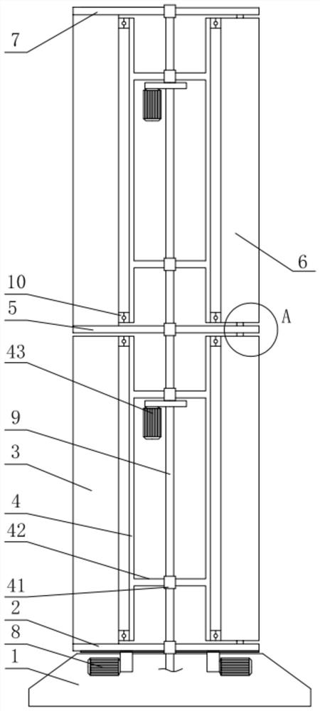
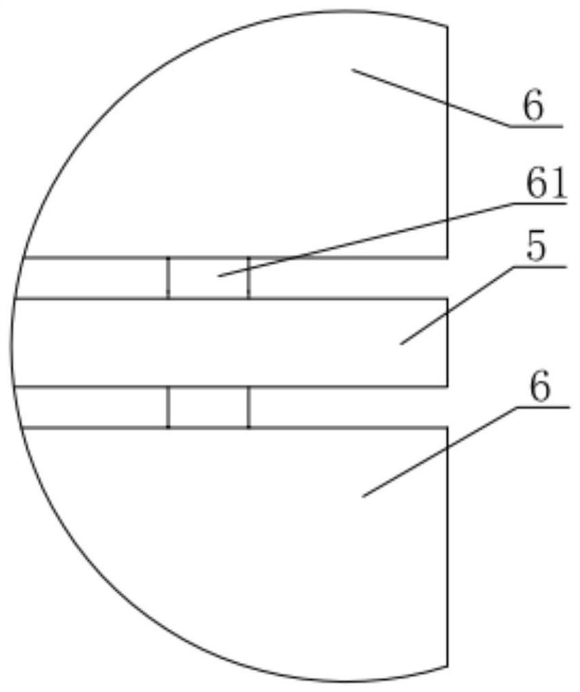
[0032] Such as figure 1 and figure 2 As shown, a marine diversion type wind power boosting device of this embodiment includes a base 1, a rotating shaft 9 is fixed vertically at the center of the base 1, and a rotating body 4 is circumferentially sleeved on the rotating shaft 9 above the base 1. , the rotating body 4 rotates relative to the rotating shaft 9 under the drive of the rotor power mechanism 43; the front and rear of the rotating body 4 above the base 1 are respectively equipped with a diversion body 3 and an empennage 6, and the diversion body 3 and the empennage 6 are controlled by the diversion power mechanism 8 drives each to swing with the axial direction of the rotating shaft 9 as the center of the circle;

[0033] Through the swing of the deflector 3 and the empennage 6, the cross-sectional structure of the booster equi...


PUM


Abstract

The invention relates to a marine diversion type wind power boosting device, which comprises a base, a rotating shaft is fixed vertically at the center of the base, and a rotating body is sleeved on the rotating shaft above the base, and the rotating body is driven by a rotor power mechanism to face each other. It rotates on the axis of rotation; the front and rear of the rotating body above the base are respectively equipped with diverters and tail fins, which are driven by the diversion power mechanism to swing around the axis of the rotation axis; They are all connected by rotation; the surface pressure distribution is adjusted by the swing of the deflector and the empennage to control the lift direction of different wind speeds and wind directions, which greatly improves the thrust provided for the ship, reduces the influence of lateral force, and effectively improves the wind direction of different wind speeds. The lower adaptability; and the deflector and the empennage form the supporting structure of the rotating body to ensure the stability of the internal rotating body and effectively reduce the rotating speed and energy consumption of the rotating body.

Description

technical field [0001] The invention relates to the technical field of ship wind power boosting equipment, in particular to a ship diversion type wind power boosting equipment. Background technique [0002] At present, the requirements of the International Maritime Organization for the energy efficiency of ships are continuously increasing, and innovative means such as the use of wind energy and efficient drag reduction have become important technical means to improve the energy efficiency of ships and reduce carbon emissions. In recent years, wind boosting equipment such as hard wing sails and Magnus rotors have been applied to real ships, providing new technical means for energy saving and emission reduction of ships. At the same time, improving the boosting effect and scope of application of wind boosting equipment and reducing its impact on ships has become a technical issue that requires special attention in the process of development and innovation of wind boosting equ...

Claims


Application Information

Patent Timeline
Patent Type & Authority Patents(China)
IPC IPC(8): B63H9/06
CPCB63H9/06Y02T70/5236B63H9/02
Inventor 刘希洋胡世良王艳霞陈京普郑安燃
Owner CHINA SHIP SCIENTIFIC RESEARCH CENTER (THE 702 INSTITUTE OF CHINA SHIPBUILDING INDUSTRY CORPORATION)
Why Eureka
Try Eureka