
Efficient painting device for building wall

A high-efficiency, wall-mounted technology, applied in the direction of construction and building structure, can solve the problems of inconvenient handling, large size of the device, and difficulty in painting the building walls, and achieve the effect of improving the painting effect and the convenient transportation process.

Pending Publication Date: 2021-07-02
DESIGN INST NO 9 MINISTRY OF MECHINE BUILDING
View PDF14 Cites 0 Cited by
  • Summary
  • Abstract
  • Description
  • Claims
  • Application Information

AI Technical Summary

Problems solved by technology

But this device has the following disadvantages: 1, only vertical building walls can be painted, and horizontal building walls cannot be painted and uneven building walls are difficult to paint; 2, the device has a large volume and is inconvenient to carry

Method used


Image

  • Efficient painting device for building wall
  • Efficient painting device for building wall
  • Efficient painting device for building wall

Examples


Embodiment 1

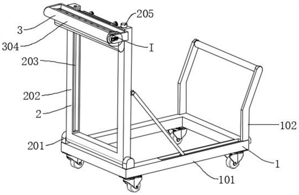
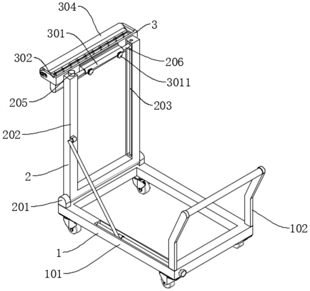
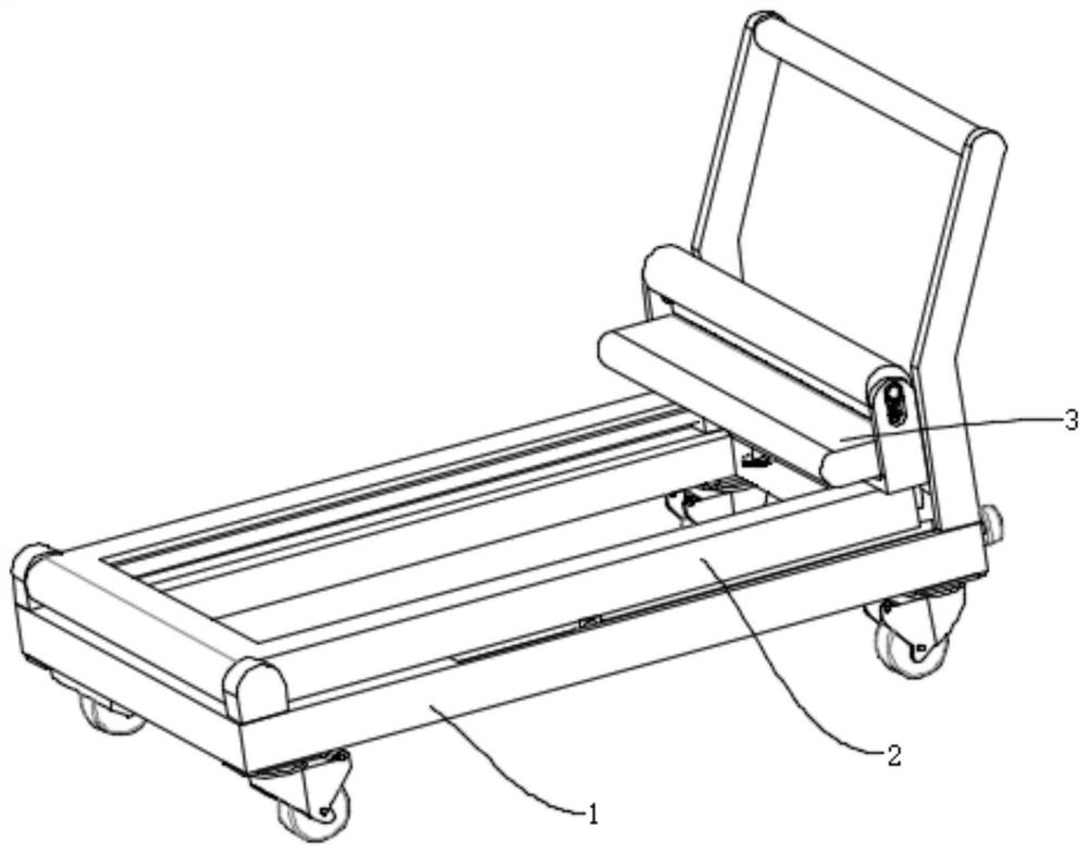
[0039] Such as Figure 1-Figure 9 As shown, the present invention is used for a high-efficiency painting device for building walls, including a moving mechanism 1 , a folding mechanism 2 and a painting mechanism 3 . One side of the moving mechanism 1 is provided with a folding mechanism 2 , and the side of the folding mechanism 2 away from the moving mechanism 1 is rotatably connected with a painting mechanism 3 .

[0040]Described folding mechanism 2 comprises rotating base 201, support 202, stabilizing bar 203, the first transmission screw 204, motor 205 and moving rod 206, rotating base 201 is connected to moving mechanism 1 top front side two ends by bolt, rotating base 201 A support 202 is connected between them through the damping rotation of the pin shaft, and the support 202 is a U-shaped structure. The inner side of one of the columns of the bracket 202 is provided with a first chute, the inner side of the first chute is connected with the first transmission screw 20...

Embodiment 2

[0048] Such as Figure 10 As shown, the difference between Embodiment 2 and Embodiment 1 is that: the support mechanism 4 includes a second support rod 41, a second fixed block 42, and a slot 43, the slot 43 is set on the top of the flatbed truck 101, and the inside of the slot 43 is snapped There is a second support rod 41, and the end of the second support rod 41 away from the draw-in groove 43 is provided with an elbow, which is inserted into the inner side of the second fixed block 42, and the second fixed block 42 is welded on the bracket 202, so that the In order to support the function of the bracket 202, when one end of the second support rod 41 is plugged into the inner side of the second fixing block 42 and the other end is engaged in the inner side of the slot 43, the bracket 202 is in a vertical state.

[0049] In the above structure, when in use, first move the device to a suitable position, then rotate the bracket 202 so that the bracket 202 is in a vertical stat...


PUM


Abstract

The invention discloses an efficient painting device for a building wall. The efficient painting device comprises a moving mechanism, a folding mechanism and a painting mechanism; the folding mechanism is arranged on one side of the moving mechanism; the painting mechanism is rotatably connected to the side, away from the moving mechanism, of the folding mechanism; the folding mechanism comprises rotating seats, a support, a stabilizing rod, a first transmission lead screw, a motor and a moving rod; and the rotating seats are connected to the two ends of one side of the top of the moving mechanism through bolts. The size of the whole device can be changed, so that the device is more convenient to carry; a painting roller can be located at the highest position or the lowest position of the whole painting mechanism, and painting of a horizontal building wall and painting of the bottom of a vertical building wall are achieved; and the painting roller can be extruded through an elastic extrusion assembly, so that certain pressure exists between the painting roller and the building wall all the time, and the painting effect is improved accordingly.

Description

technical field [0001] The invention belongs to the technical field of building wall painting, in particular to a high-efficiency painting device for building walls. Background technique [0002] Whitewashing refers to tools for cleaning or painting made of bundles of palms, such as brushes, brushes, scrub brushes, especially tools for makeup and powder or protective layers applied to the surface of buildings. [0003] Building construction refers to the production activities in the implementation stage of engineering construction. It is the construction process of various buildings. It can also be said to be the process of turning various lines on the design drawings into real objects at designated locations. It includes basic engineering construction, main structure construction, roofing engineering construction, decoration engineering construction, etc. The place of construction work is called "building construction site" or "construction site", also called construction s...

Claims


Application Information

Patent Timeline
Patent Type & Authority Applications(China)
IPC IPC(8): E04F21/08
CPCE04F21/08
Inventor 孙俭波雷光远李克岩乔鲲鹏
Owner DESIGN INST NO 9 MINISTRY OF MECHINE BUILDING
Learn More