Drilling screw

A technology of drilling tail screws and drill bodies, which is applied in the direction of screws, threaded fasteners, connecting components, etc., and can solve the problems of reduced positioning effect, increased resistance, and skew

Active Publication Date: 2022-06-24
TAIWAN SHAN YIN INT CO LTD
View PDF6 Cites 0 Cited by
  • Summary
  • Abstract
  • Description
  • Claims
  • Application Information

AI Technical Summary

Problems solved by technology

[0003] Furthermore, the design of the included angle 134α of the drill portion 134 will affect the sharpness of the drill edge 135 and the drill portion 134 itself. The sharpness makes it easier for the drill part 134α to penetrate into the object, and the initial positioning effect is better, but the area of ​​the drill edge 135 will be reduced to reduce the cutting effect, and even lead to the inability to smoothly drive the drill tail screw 1 into the lock. Therefore, the included angle 134α is usually designed to be above 120 degrees, but relatively it will cause the sharpness of the drill part to decrease, which will reduce the positioning effect
[0004] Furthermore, when the drill end screw 1 is initially locked, it only forms a fulcrum contact with the surface of the lock through the drill portion 134. If the surface of the lock is smooth, the friction generated by it will Smaller, therefore, if the drill part 134 is not sharp enough, the drill part 134 will not be able to effectively hold on to the lock, so that the drill end screw 1 will easily slip during the screwing process, resulting in deviation and skew Phenomenon, not only will cause the lock setting to be skewed and difficult to lock, but will also cause inconvenience in the locking operation, and will also damage the surface of the lock during the locking process; in addition, during the locking process, it uses the second drill edge 135 to cut Locking, its chips will be cut from the center of the second drill edge 135 and produce chips, and its chips are easy to accumulate and block the entrance of the chip flute 133, causing increased resistance. The situation that the outward expansion and extrusion caused the lock to crack the material needs to be improved.

Method used


Image

  • Drilling screw
  • Drilling screw
  • Drilling screw

Examples


Embodiment Construction

[0041] The above and other technical contents, features and effects of the present invention will be clearly understood in the following detailed description of the preferred embodiments with reference to the drawings.

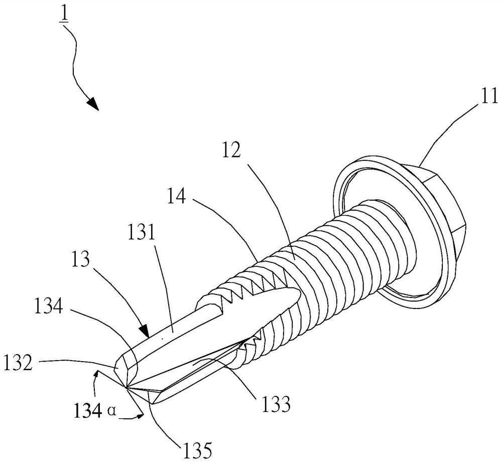
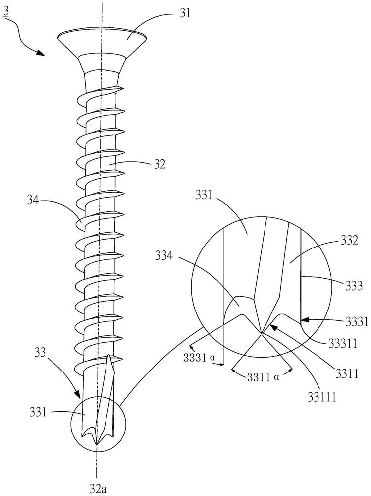
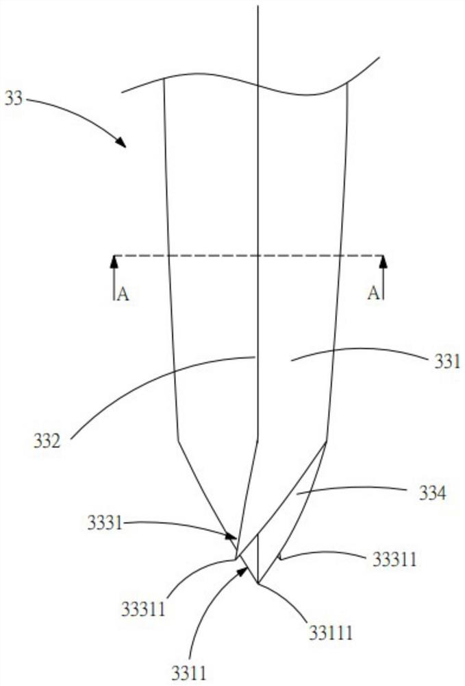
[0042] see figure 2 , the first preferred embodiment of the drill bit screw 3 of the present invention, the drill bit screw 3 includes a screw head 31, a rod body 32 extending outward from the screw head 31, and a rod body 32 provided on the rod body 32 and opposite the screw A drill tail portion 33 at one end of the head 31, and a plurality of threads 34 provided with a spiral ring on the rod body 32; wherein, the drill tail portion 33 has a drill body 331 extending outward from the rod body 32, which are respectively formed on the drill body Chip flutes 332 are staggered on both sides of the 331 , and a cutting edge 333 is formed at the connection between the drill body 331 and the chip flutes 332 .

[0043] image 3 , Figure 4 , Figure 5 , the drill ...


PUM


Abstract

The invention discloses a tail-drilling screw, which mainly consists in that a drill part is formed at the end of the drill body, and the tip parts which are respectively formed on both sides of the drill body and connected with the cutting edge are respectively recessed on the drill body. And a concave arc surface extending from the drill part to the tip; wherein the drill part is located on the center of the rod body, and the angle between the drill parts does not exceed 60 degrees, and the protrusion length of the drill part is greater than that of the tip parts At the same time, the angle between the tips does not exceed 50 degrees; therefore, through the design of the drill part, the tip and the concave arc surface, the tail end of the drill body forms a chord cutting state, so that the two cutting edges and the tip can be in the Under the positioning of the drill part, the drill part is positioned accurately and quickly, and the sharp cutting is screwed into the outside, and the concave arc surface and the chip removal groove can quickly provide chip removal, effectively avoiding the resistance and cracking caused by chip accumulation.

Description

technical field [0001] The invention relates to a screw, in particular to a drill tail screw. Background technique [0002] see figure 1 , the known drill bit screw 1 includes a screw head 11, a rod body 12 extending outward from the screw head 11, a drill tail portion 13 provided on the rod body 12 and opposite to one end of the screw head 11, and a plurality of helical ring devices The screw thread 14 on the rod body 12; wherein, the drill tail portion 13 has a drill body 131 extending outward from the rod body 12, an inclined drill tail 13 extending outward from the drill body 131, and at least one A chip removal groove 133 is formed on the drill body 131 , the drill tail 132 , and a drill portion 134 located at the end edge of the drill tail 132 , and two drill holes are formed at the connection between the chip removal groove 133 and the drill body 131 . and the drill edges 135 are arranged on both sides of the drill portion 134; therefore, the drill portion 134 is in...

Claims


Application Information

Patent Timeline
Patent Type & Authority Patents(China)
IPC IPC(8): F16B25/04F16B25/10
CPCF16B25/103
Inventor 苏国材苏昱荣
Owner TAIWAN SHAN YIN INT CO LTD
Why Eureka
Try Eureka