SAR imaging scene division method based on region-of-interest detection

A technology for imaging scenes and regions of interest, which is applied in the field of SAR imaging scene division based on region of interest detection, can solve the problems of serious defocus, huge amount of calculation, large phase error, etc., to improve imaging quality, ensure focusing effect, and improve calculation speed effect

Active Publication Date: 2021-07-02
UNIV OF ELECTRONICS SCI & TECH OF CHINA
View PDF6 Cites 3 Cited by
  • Summary
  • Abstract
  • Description
  • Claims
  • Application Information

AI Technical Summary

Problems solved by technology

However, when imaging a large scene, the phase error between the center of the scene and the edge of the scene is relatively large. If it is divided uniformly, the edge of the imaging scene will still produce serious defocusing. If it is divided by phase error gradient, although it can be more accurate Imaging results, but the amount of calculation is extremely large

Method used


Image

  • SAR imaging scene division method based on region-of-interest detection
  • SAR imaging scene division method based on region-of-interest detection
  • SAR imaging scene division method based on region-of-interest detection

Examples


Embodiment Construction

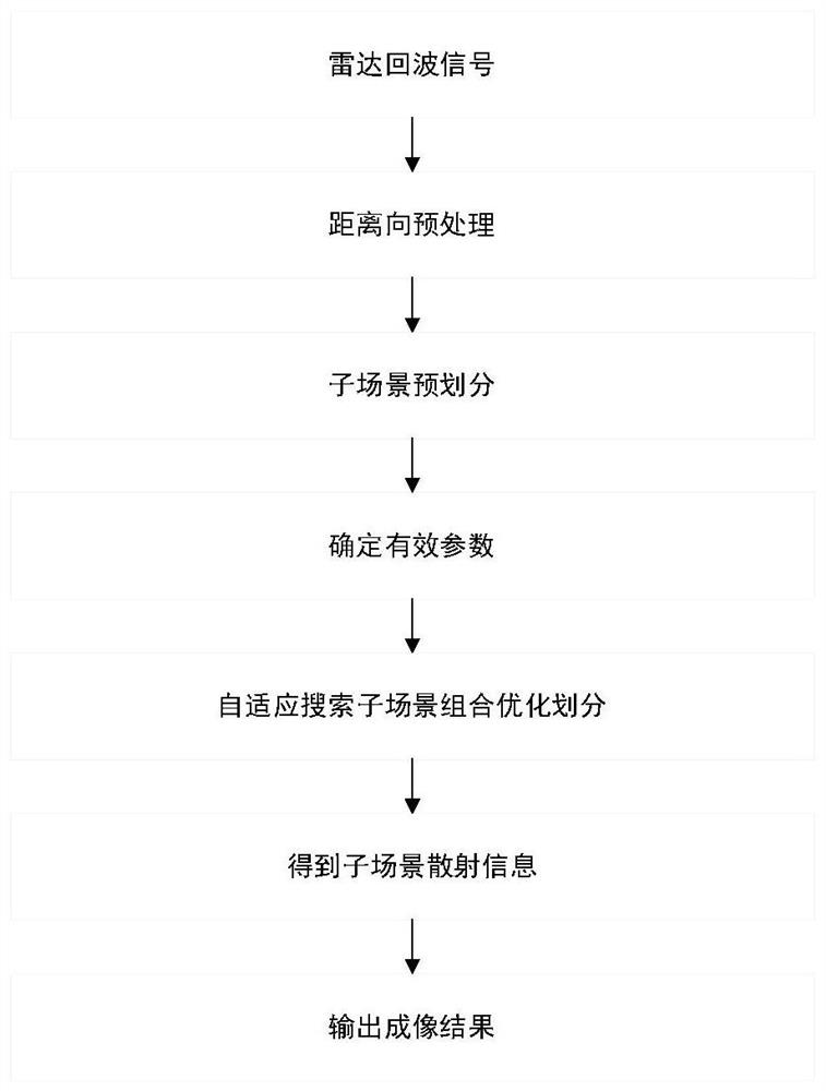
[0021] The present invention will be described in detail below in conjunction with the accompanying drawings and simulation examples to prove the practicability of the present invention.

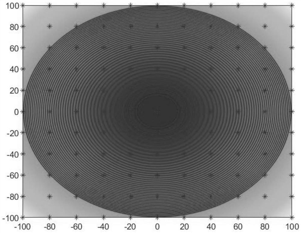
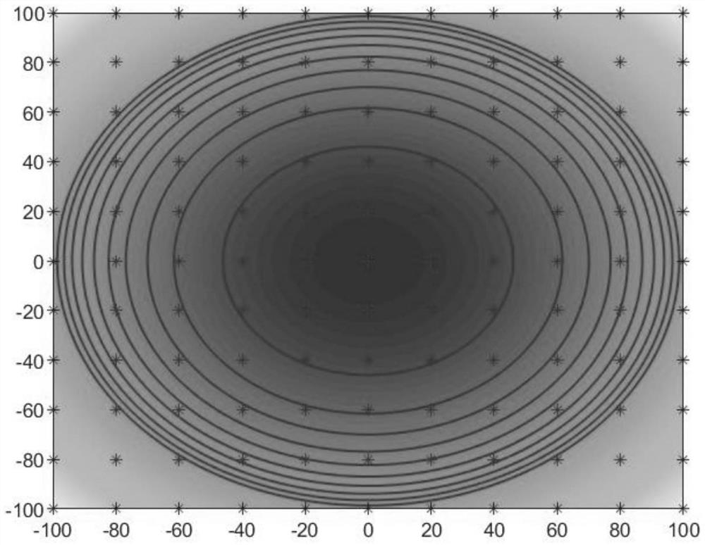
[0022] as attached figure 1 As shown, through a SAR imaging scene division method based on region of interest detection of the present invention, the input SAR original echo can be processed by imaging to effectively suppress the defocusing phenomenon at the edge of the scene. The specific implementation steps are as follows:

[0023] Step 1: Preprocess the original echo in the distance direction: the received signal s(τ,t) and the reference signal s ref (τ,t) mixed to get the difference frequency signal s if (τ,t), its expression is:

[0024]

[0025] where R a (t) is the reference slope distance, △R(t)=R t (t)-R ref (t), T p is the pulse width of the signal, τ is the fast time of the radar signal, t is the slow time of the radar signal, c is the speed of light, α is the frequency ...


PUM


Abstract

The invention belongs to the technical field of radar imaging, and relates to an SAR imaging scene division method based on region-of-interest detection. According to the method, through analyzing the phase error obtained after the echo data of a synthetic aperture radar is preprocessed, and further optimizing a sub-scene division method based on an existing phase gradient sub-scene division method, a region of interest can be well focused, the edge defocusing can be inhibited, and the imaging quality can be improved. In addition, the method does not involve complex calculation operation, and the implementation mode of the method is relatively simple.

Description

technical field [0001] The invention belongs to the technical field of radar imaging, and in particular relates to a SAR imaging scene division method based on region of interest detection. Background technique [0002] Synthetic Aperture Radar (SAR) utilizes the correlation of radar echo signals to accumulate the Doppler shift of echo signals during radar motion, and synthesizes equivalent radar apertures in the direction of radar motion to achieve high-resolution imaging . It can realize all-day and all-weather regional monitoring and imaging. Motion is the basis of SAR and the source of problems. Motion error is the main source of phase error. The primary phase error only affects the position of the signal, and the secondary phase error will defocus the image and affect the imaging quality. High-order phase error will cause false alarms. [0003] The phase errors caused by motion errors are generally two-dimensional space-varying and coupled. The solution to space-vary...

Claims


Application Information

Patent Timeline
Patent Type & Authority Applications(China)
IPC IPC(8): G01S13/90G01S7/41G06F17/14
CPCG01S13/9021G01S7/41G06F17/14
Inventor 皮亦鸣李晋闵锐王旭杨晓波曹宗杰崔宗勇
Owner UNIV OF ELECTRONICS SCI & TECH OF CHINA
Why Eureka
Try Eureka