
Safety monitoring device for electrical engineering

A safety monitoring and electrical engineering technology, applied in the direction of measuring devices, signal devices, electrical components, etc., can solve the problems of inconvenient installation and disassembly, electrical equipment hazards, large size, etc., to achieve easy installation and disassembly, easy maintenance and maintenance, Easy to adjust effects

Pending Publication Date: 2021-07-02
NORTH CHINA ELECTRIC POWER UNIV (BAODING)
View PDF0 Cites 0 Cited by
  • Summary
  • Abstract
  • Description
  • Claims
  • Application Information

AI Technical Summary

Problems solved by technology

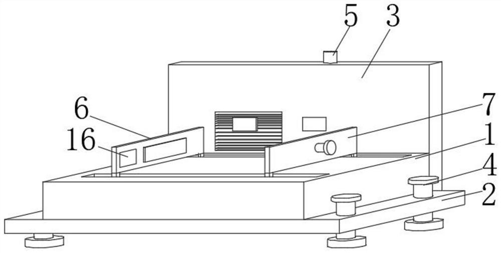
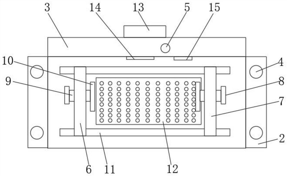
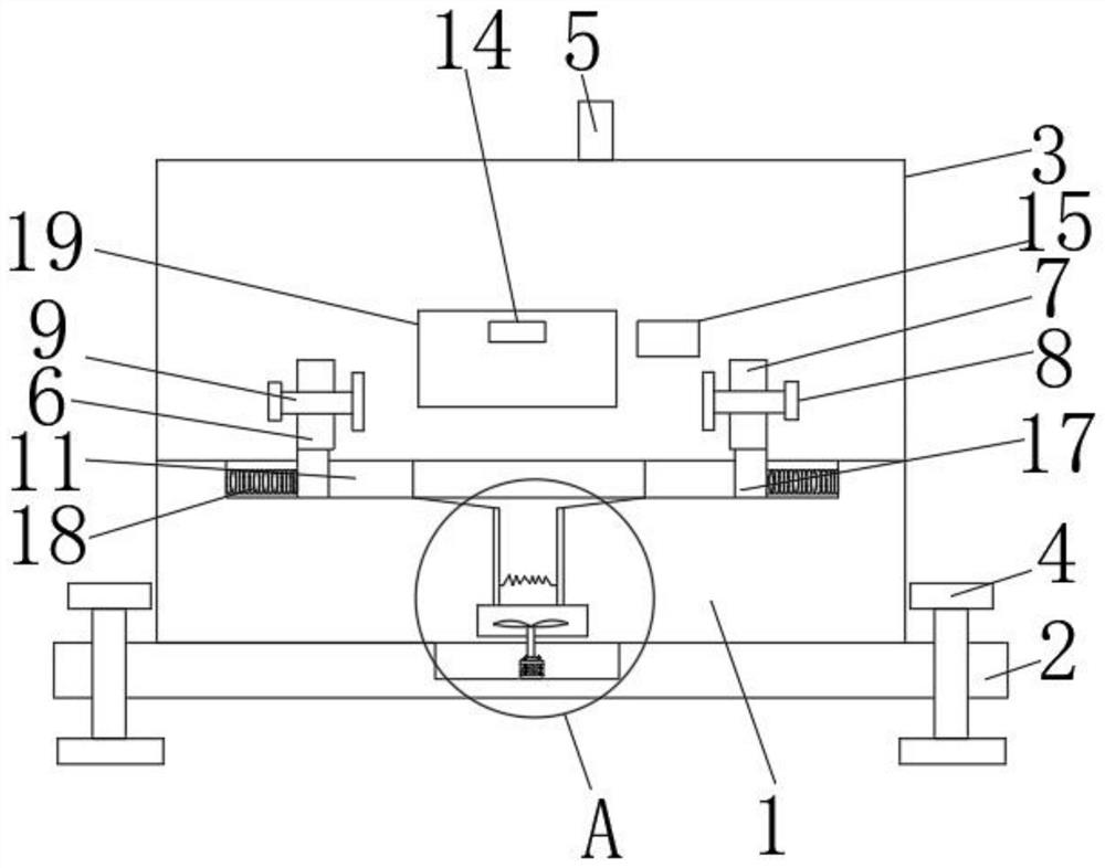
[0004] The purpose of the present invention is to overcome the large size of the current electrical engineering safety monitoring device existing in the prior art, which can only monitor and process large-scale electrical boxes, and is not convenient for installation and disassembly, and it is not convenient for technicians to use it in the later stage Overhauling the monitoring device has brought more difficulties to the technicians, and the environment where the electrical equipment is placed is complicated. When the electrical equipment works in a dark and humid place for a long time, it will cause its moisture to be too heavy, making the The bottom of electrical equipment is easy to get wet, which will cause harm to electrical equipment. To provide a safety monitoring device for electrical engineering. The safety monitoring device for electrical engineering has the effect of dehumidification and easy installation

Method used


Image

  • Safety monitoring device for electrical engineering
  • Safety monitoring device for electrical engineering
  • Safety monitoring device for electrical engineering

Examples


Embodiment Construction

[0023] Specific embodiments of the present invention will be described in detail below in conjunction with the accompanying drawings. It should be understood that the specific embodiments described here are only used to illustrate and explain the present invention, and are not intended to limit the present invention.

[0024] In the description of the present invention, it should be noted that the terms "upper", "lower", "inner", "outer", "front end", "rear end", "both ends", "one end", "another end" ” and other indicated orientations or positional relationships are based on the orientations or positional relationships shown in the accompanying drawings, which are only for the convenience of describing the present invention and simplifying the description, rather than indicating or implying that the referred device or element must have a specific orientation, with a specific configuration and operation, and therefore should not be construed as limiting the invention. In addit...


PUM


Abstract

A safety monitoring device for electrical engineering disclosed by the present invention comprises a supporting plate; a bottom plate is fixedly connected to the lower end of the surface of the supporting plate, fixing bolts are arranged at the upper ends of the surfaces of the two sides of the bottom plate, a motor is fixedly connected to the interior of a groove, and a transmission shaft is in transmission connection to the upper end of the surface of the motor. A wind wheel is fixedly connected to the upper end of the surface of the transmission shaft, an air guide pipe is arranged at the upper end of the surface of the wind wheel, a breathable plate is fixedly connected to the side, away from the wind wheel, of the air guide pipe, and an electric heating wire is arranged in the air guide pipe. a motor is arranged and controls a transmission shaft to rotate to drive a wind wheel to rotate; the electric heating wire enables generated hot air to pass through the air guide pipe and then to be exhausted through the air holes formed in the surface of the air permeable plate, and therefore the dehumidification effect on the electrical equipment is achieved; through arrangement of the fixing bolts, the safety monitoring device for the electrical engineering is convenient to mount and dismount, and a technician can conveniently repair and maintain the safety monitoring device in the later period.

Description

technical field [0001] The invention relates to the technical field of electrical engineering, in particular to a safety monitoring device for electrical engineering. Background technique [0002] Traditionally, electrical engineering has been defined as the sum total of related disciplines used to create electrical and electronic systems. This definition was originally very broad, but with the rapid development of science and technology, the current concept of electrical engineering has gone far beyond the scope of the above definition. The discipline of electrical engineering, also known as the Department of Electrical Engineering, the Department of Electrical Engineering and Information Science, the Department of Electrical Engineering and Computer Science, etc., mainly focuses on computer and information technology. [0003] The current safety monitoring devices for electrical engineering are large in size and can only monitor large electrical boxes, and it is not easy ...

Claims


Application Information

Patent Timeline
Patent Type & Authority Applications(China)
IPC IPC(8): H05K7/20H05K5/02G08B5/36G08B21/18G01D21/02
CPCG01D21/02G08B5/36G08B21/182H05K5/0217H05K7/20
Inventor 王鸣誉
Owner NORTH CHINA ELECTRIC POWER UNIV (BAODING)
Learn More