A vehicle floor structure
A base plate and vehicle technology, applied to vehicle components, vehicle energy storage, vehicles used for freight, etc., to achieve the effect of easy maintenance and reduced deformation
Active Publication Date: 2022-06-03
重庆骏普康实业有限公司
View PDF11 Cites 0 Cited by
- Summary
- Abstract
- Description
- Claims
- Application Information
AI Technical Summary
Problems solved by technology
[0006] Aiming at the deficiencies of the prior art, the present invention provides a vehicle floor structure that reduces the deformation of the floor after being impacted by the outside and is easy to maintain
Method used
View moreImage
Smart ImageViewing Examples
Examples
Embodiment
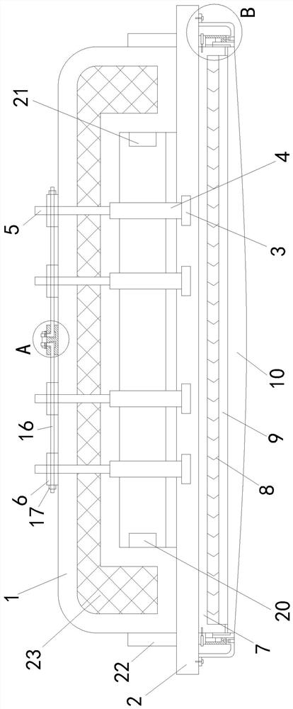
[0028] Please refer to Figures 1-6, a vehicle floor structure, comprising a floor body 1, the interior of the floor body 1 is provided with a cavity,
Login to View More PUM
 Abstract
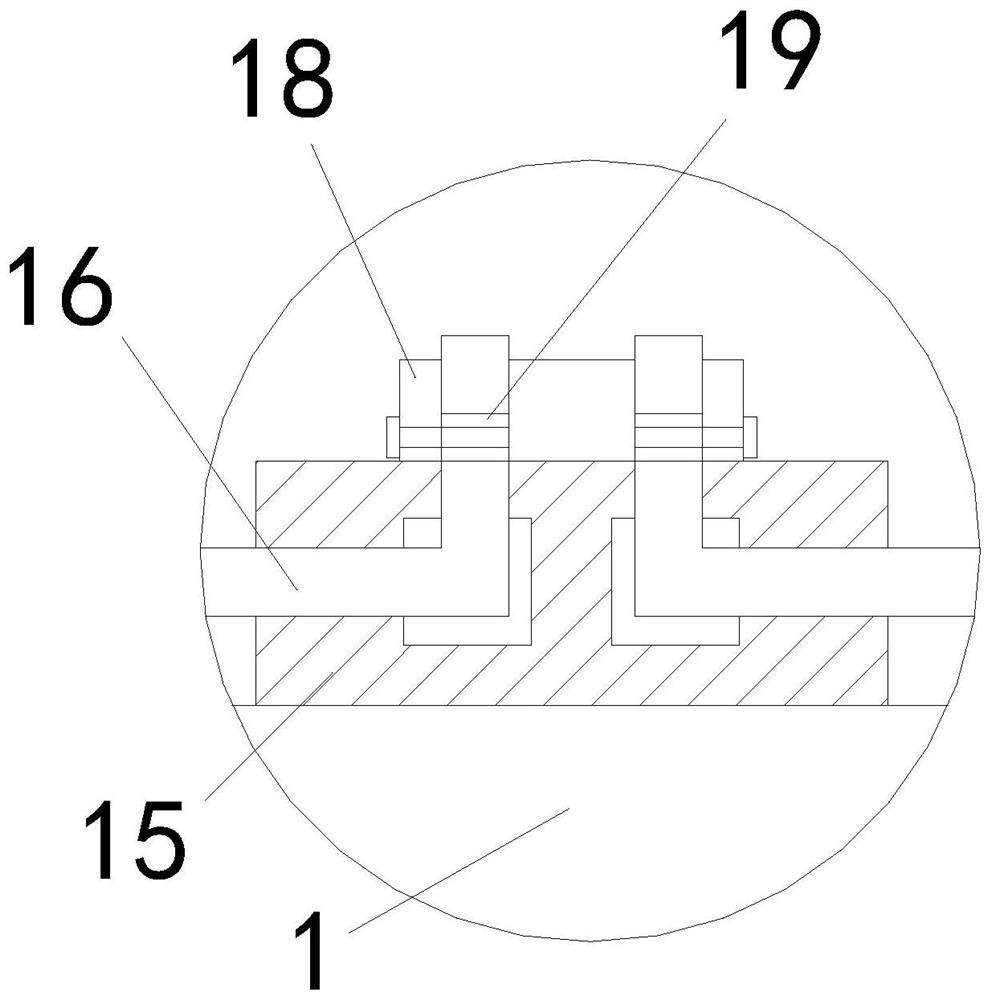
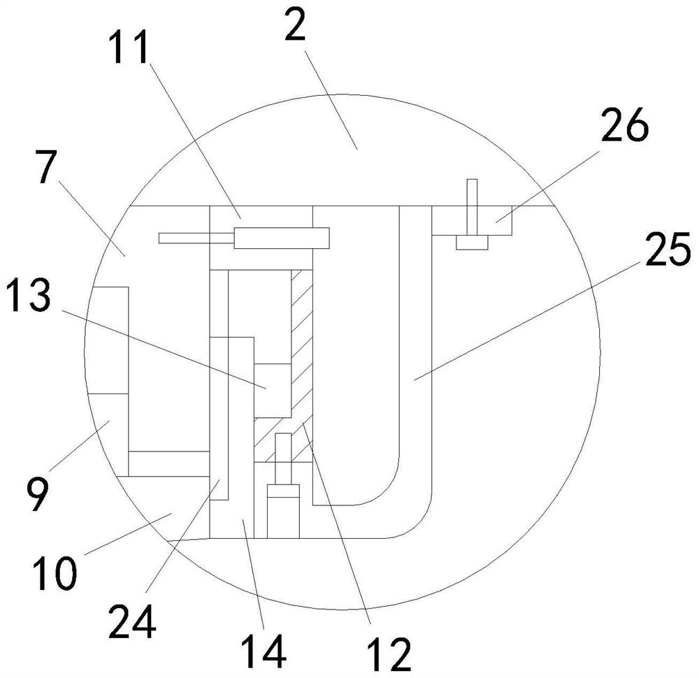
The present invention relates to the field of vehicle floor technology, specifically a vehicle floor structure, including a floor body, an adapter plate, a circular plate, a support shaft, a screw, and a limiting plate. The top of the body is equipped with a limit device, the bottom of the adapter plate is fixedly connected to the support box, the top of the inner wall of the support box is fixedly connected to multiple springs, the bottom of the support box slides up and down to cooperate with a positioning plate, and the top of the positioning plate is fixedly connected to the bottom of each spring. The bottom of the positioning plate is fixedly connected with a protective plate, the left and right ends of the support box are connected with a horizontal plate by screws, the bottom of each horizontal plate is fixedly connected with a longitudinal plate, and each longitudinal plate is provided with a limit slot at the end close to the middle of the adapter plate. Each limit slot slides up and down to cooperate with a sliding block, and the end of the sliding block close to the middle part of the adapter plate is fixedly connected with a support plate; it reduces the deformation of the bottom plate after being impacted by the outside, and is convenient for maintenance.
Description
A vehicle floor structure technical field [0001] The present invention relates to the technical field of vehicle floor panels, in particular to a vehicle floor panel structure. Background technique [0002] The vehicle floor plays a role in supporting the goods inside the vehicle. During the use of the vehicle, due to the high Different low, after the bottom plate is impacted by the outside world, the bottom plate will be deformed, which is not conducive to the use of the bottom plate. After searching, the patent of patent publication number CN103339021A discloses a kind of vehicle floor structure, its main body structure [0003] is constructed as a double-layer structure comprising two panels formed of thermoplastic fiber-reinforced composite materials; in the area where the double-layer structure extends In the domain, each panel has at least two continuous reinforcement structures with convex open cross-sections; reinforcement structures in at least two locations T...
Claims
Login to View More Application Information
Patent Timeline
 Patent Type & Authority Patents(China)
IPC IPC(8): B60P7/08
CPCB60P7/0892Y02T10/70
Inventor 邓鸣鸣
Owner 重庆骏普康实业有限公司
Features
- R&D
- Intellectual Property
- Life Sciences
- Materials
- Tech Scout
- Unparalleled Data Quality
- Higher Quality Content
- 60% Fewer Hallucinations
Learn More Browse by: Latest US Patents, China's latest patents, Technical Efficacy Thesaurus, Application Domain, Technology Topic, Popular Technical Reports.
© 2025 PatSnap. All rights reserved.Legal|Privacy policy|Modern Slavery Act Transparency Statement|Sitemap|About US| Contact US: help@patsnap.com


