Automatic feeding device of metal decorating machine for machining metal decorating products

A technology for automatic feeding and iron printing machines, which is applied in the direction of conveyor control devices, conveyors, mechanical conveyors, etc., and can solve problems affecting the quality of iron printing, impact deformation of the front end of iron printing, and low processing efficiency.

Pending Publication Date: 2021-07-06
ANHUI HONGYANG PACKAGING GRP
View PDF5 Cites 1 Cited by
  • Summary
  • Abstract
  • Description
  • Claims
  • Application Information

AI Technical Summary

Problems solved by technology

[0005] Aiming at the deficiencies of the prior art, the present invention provides an automatic feeding device for iron printing machines for processing printed iron products, which can provide anti-collision buffer for printed iron products, effectively prevent the impact deformation of printed iron caused by the inertia of conveying, and do not need subsequent corrections. The advantages of indirectly improving the overall processing

Method used


Image

  • Automatic feeding device of metal decorating machine for machining metal decorating products
  • Automatic feeding device of metal decorating machine for machining metal decorating products
  • Automatic feeding device of metal decorating machine for machining metal decorating products

Examples


Embodiment Construction

[0023] The following will clearly and completely describe the technical solutions in the embodiments of the present invention with reference to the accompanying drawings in the embodiments of the present invention. Obviously, the described embodiments are only some, not all, embodiments of the present invention. Based on the embodiments of the present invention, all other embodiments obtained by persons of ordinary skill in the art without making creative efforts belong to the protection scope of the present invention.

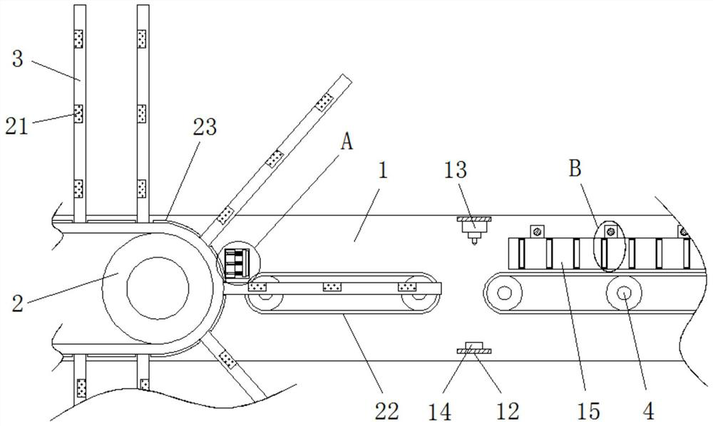
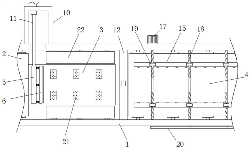
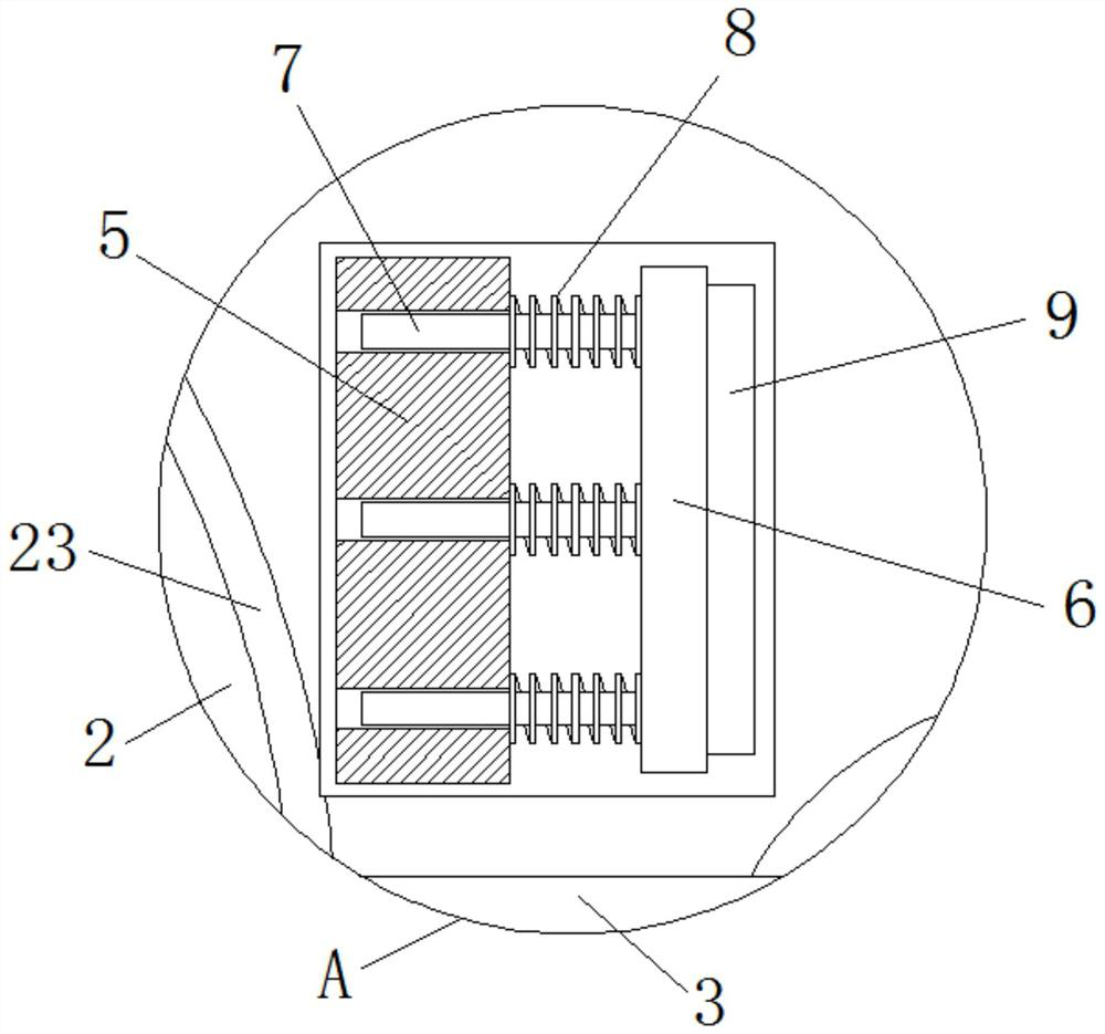
[0024] see Figure 1-4 , an automatic feeding device for an iron printing machine for processing iron printing products, including a frame 1, an overturning conveying assembly 2 is provided on the left side of the inside of the rack 1, and the surface of the conveying chain of the overturning conveying assembly 2 is fixedly connected with a plurality of evenly distributed placement Frame 3, the inside of frame 1 is located on the right side of the overturning ...


PUM


Abstract

The invention relates to the technical field of metal decorating product machining, and discloses an automatic feeding device of a metal decorating machine for machining metal decorating products. The automatic feeding device comprises a rack, wherein an overturning conveying assembly is arranged on the left side of the interior of the rack, a plurality of evenly-distributed placing frames are fixedly connected to the surface of a conveying chain of the overturning conveying assembly, a horizontal conveying assembly is arranged at the position, located on the right side of the overturning conveying assembly, in the rack, a conveying belt of the horizontal conveying assembly is located on the right side of the placing frames, a movable plate is movably arranged at the position, located on the right side of the overturning conveying assembly, in the rack, a buffer plate is arranged on the right side of the movable plate, and the left end of the buffer plate is fixedly connected with a plurality of uniformly distributed sliding rods. According to the automatic feeding device of the metal decorating machine for machining the metal decorating products, anti-collision buffering can be conducted on the metal decorating products, the phenomenon of metal decorating impact deformation caused by conveying inertia is effectively prevented, the overall machining efficiency is indirectly improved, meanwhile, the metal decorating products can be prevented from moving and deviating, and the application range is wide.

Description

technical field [0001] The invention relates to the technical field of iron printing products processing, in particular to an automatic feeding device for an iron printing machine for processing iron printing products. Background technique [0002] Iron printing is to print patterns on tinplate (tin-plated sheet), mainly using the physical properties of water and ink to repel each other, with the help of printing pressure, the printing plate is transferred to the tinplate through the blanket, which belongs to the principle of lithographic offset printing. This process has special requirements for ink. [0003] At present, when printed iron products are processed by the iron printing machine, the assembly line needs to turn the flat printed iron products into a vertical state when feeding, so as to facilitate subsequent processing. When turning over, usually the flat printed iron products are conveyed The belt is transported to the reversing conveyor belt for automatic rever...

Claims


Application Information

Patent Timeline
IPC IPC(8): B65G47/22B65G37/00B65G43/08B65G47/74B65G47/252B65G17/12B65G17/32
CPCB65G47/22B65G37/00B65G43/08B65G47/74B65G47/252B65G17/123B65G17/32B65G2201/022B65G2203/044
Inventor 朱钧金刚李永喜周光荣
Owner ANHUI HONGYANG PACKAGING GRP
Why Eureka
Try Eureka