Oil separation device for rotary compressor and compressor with same

A technology of a rotary compressor and a separation device, applied in the field of compressors, can solve the problems of oil droplet crushing and increased oil discharge, etc.

Active Publication Date: 2021-07-06
XI AN JIAOTONG UNIV
View PDF4 Cites 2 Cited by
  • Summary
  • Abstract
  • Description
  • Claims
  • Application Information

AI Technical Summary

Problems solved by technology

[0005] In order to overcome the above technical problems, the present invention proposes a rotary compressor oil separation device and a compressor with the device, which solves the problem that the oil droplets are b

Method used


Image

  • Oil separation device for rotary compressor and compressor with same
  • Oil separation device for rotary compressor and compressor with same
  • Oil separation device for rotary compressor and compressor with same

Examples


Embodiment Construction

[0026] The present invention will be described in further detail below in conjunction with the accompanying drawings.

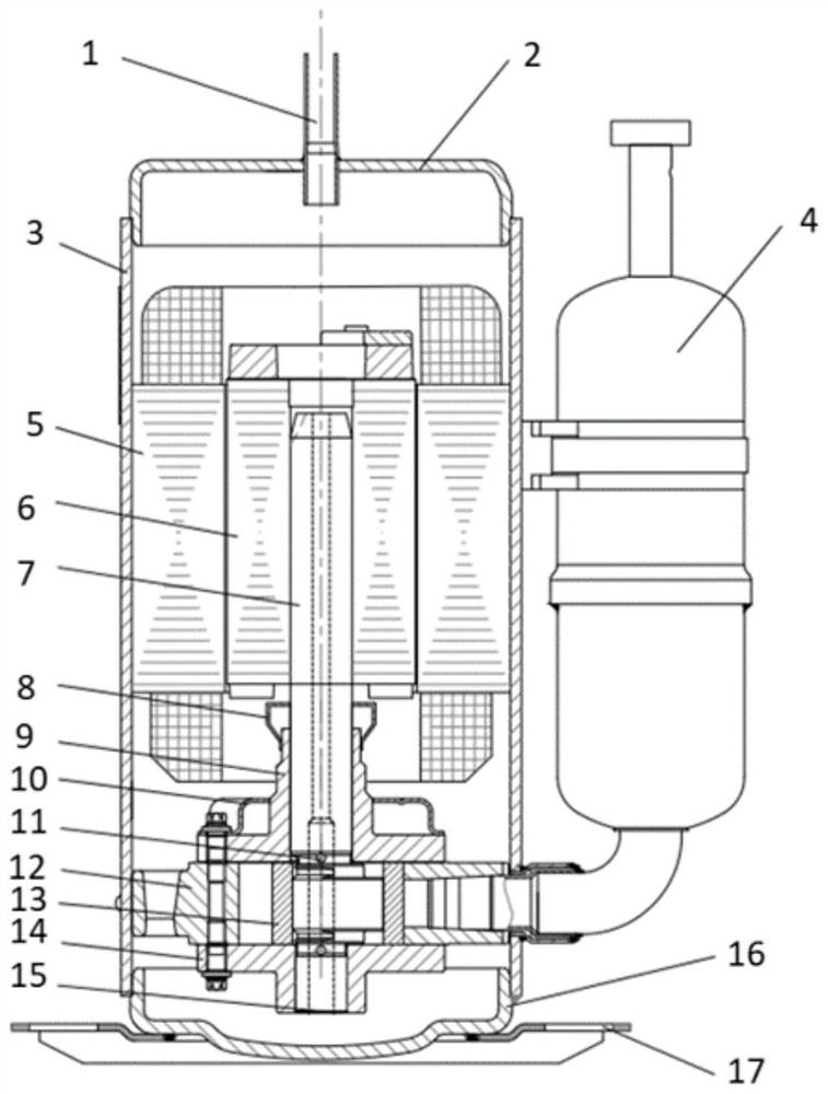
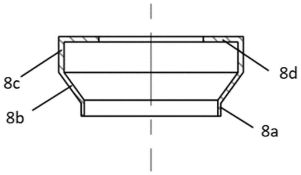
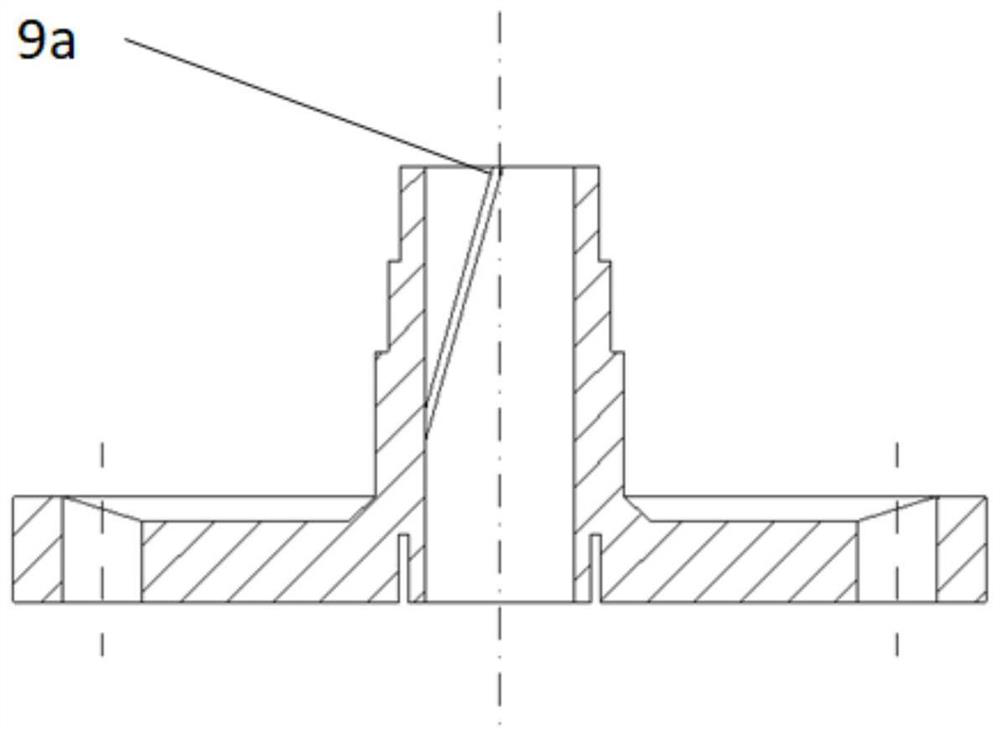
[0027] Figure 1-Figure 5 Shown: is a structural schematic diagram of a rotary compressor with the oil separation device in one of the implementation examples of the present invention, the rotary compressor includes a shell assembly, a motor assembly, a pump body assembly, a crankshaft 7 and an oil separation device Ontology8. The casing assembly includes three parts: the compressor upper cover 2 , the middle casing 3 and the compressor lower cover 16 , and the three parts of the casing are welded together to form a closed cavity. The compressor upper cover assembly is provided with an exhaust pipe 1 , the motor stator 5 is fixed on the housing assembly, and the motor rotor 6 is fixed on the crankshaft 7 and placed in the inner hole of the motor stator 5 . The pump body assembly is welded and fixed on the shell assembly, and the pump body assembly is compos...


PUM


Abstract

The invention discloses an oil separation device for a rotary compressor and a compressor with same. The oil separation device comprises an oil separation device body, wherein the oil separation device body comprises a first fixing part connected with an upper bearing, the first fixing part is connected with a first oil separation part, an oil hole is formed in the first oil separation part, and is in a horn mouth shape, the upper outer edge of the first oil separation part is connected with a second oil separation part in the axial direction, the second oil separation part is in a cylindrical shape, the second oil separation part is connected with a third oil separation part, and the third oil separation part points to a crankshaft to be in a circular ring shape. The oil separation device solves the problem that oil drops are broken and the oil discharge amount is increased due to the fact that lubricating oil is sprayed out of a spiral oil groove outlet to collide with a motor rotor is solved, and does not influence compressor power consumption.

Description

technical field [0001] The invention relates to the technical field of compressors, in particular to a rotary compressor oil separation device and a compressor with the device. Background technique [0002] In rotary compressors, lubricating oil mainly plays the role of lubrication, sealing, cleaning and noise reduction. During the operation of the compressor, the end of the crankshaft extends into the lubricating oil pool at the bottom of the compressor, and the lubricating oil is supplied to each friction pair through the oil stirring plate in the center oil hole to ensure the smooth operation of each friction pair. The upper bearing is a particularly important pair of friction pairs in each friction pair. The oil supply of the upper bearing mainly depends on the radial oil hole and the spiral oil groove. Lubricating oil supply for lubricating pair. During the operation of the compressor, especially during high-frequency operation, the amount of lubricating oil sprayed f...

Claims


Application Information

Patent Timeline
IPC IPC(8): F04C29/02F04C23/02F04C18/10
CPCF04C29/026F04C23/02F04C18/10
Inventor 吴建华李孝洋张帅万艮昌
Owner XI AN JIAOTONG UNIV
Why Eureka
Try Eureka