
Displacement measurement system based on LVDT sensor

A displacement measurement and sensor technology, applied in the field of sensors, can solve problems such as affecting the accuracy of displacement measurement

Pending Publication Date: 2021-07-06
BEIJING HANGKE ENGINE CONTROL SYST SCI & TECH +1
View PDF6 Cites 0 Cited by
  • Summary
  • Abstract
  • Description
  • Claims
  • Application Information

AI Technical Summary

Problems solved by technology

Due to the existence of zero-crossing distortion and the inconsistency of the coil characteristics of the two output sides of the LVDT sensor in the existing measurement system using the LVDT sensor, the accuracy of the displacement measurement is seriously affected. How to improve the accuracy of the displacement measurement using the LVDT sensor has become a A technical problem that needs to be solved

Method used


Image

  • Displacement measurement system based on LVDT sensor
  • Displacement measurement system based on LVDT sensor
  • Displacement measurement system based on LVDT sensor

Examples


Embodiment 1

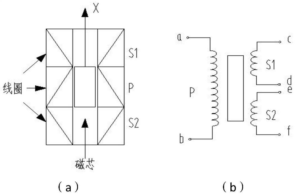
[0055] like figure 1 As shown, the present invention provides a displacement measurement system based on an LVDT sensor, and the displacement measurement system includes: an excitation signal generation module 1, an excitation signal conditioning circuit 2, an LVDT sensor 3, a two-way induction signal conditioning circuit 4 and a central processing unit 5; the excitation signal generation module 1 is connected to the excitation signal conditioning circuit 2, and the excitation signal generation module 1 is used to generate an excitation signal; the excitation signal conditioning circuit 2 is connected to the primary side coil of the LVDT sensor 3 , the excitation signal conditioning circuit 2 is used to condition the excitation signal, and output the adjusted excitation signal to the primary side coil of the LVDT sensor 3; the two secondary side coils of the LVDT sensor 3 are respectively It is connected with two described sensing signal conditioning circuits 4, and the sensin...

Embodiment 2

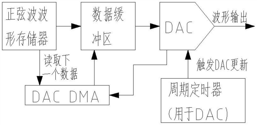
[0079] The difference between this embodiment and Embodiment 1 is that the excitation signal generation module includes a DAC conversion sub-module.

[0080] Correspondingly, the excitation signal conditioning circuit includes a second excitation signal conditioning subcircuit, and the second excitation signal conditioning subcircuit is used for conditioning an excitation signal output by a DAC conversion submodule.

[0081] like Figure 5 As shown, the second excitation signal conditioning sub-circuit includes comparator U5B, comparator U5C, resistor R11, resistor R21, resistor R31, resistor R41, resistor R51, resistor R61, capacitor C4, capacitor C52, capacitor C12, capacitor C62, capacitor C72, capacitor C82 and capacitor C83; the output end of the DAC conversion sub-module is connected to the positive input end of the comparator U5B after the resistor R11, and the positive input end of the comparator U5B is also grounded after the capacitor C42; the comparator U5B The neg...


PUM


Abstract

The invention discloses a displacement measurement system based on an LVDT sensor. The displacement measurement system comprises an excitation signal generation module, an excitation signal conditioning circuit, the LVDT sensor, an induction signal conditioning circuit and a central processing unit. The two induction signal conditioning circuits are used for conditioning the voltage output by the two secondary side coils of the LVDT sensor respectively and transmitting the voltage to the central processing unit, the central processing unit directly calculates the voltage corresponding to the displacement according to the voltage output by the two coils, zero-crossing distortion in an absolute value circuit can be eliminated, the two paths of output voltages are conditioned respectively, errors caused by inconsistent characteristics of the two coils of the sensor can be eliminated, and meanwhile the influence caused by waveform distortion can be reduced.

Description

technical field [0001] The invention relates to the technical field of sensors, in particular to a displacement measuring system based on LVDT sensors. Background technique [0002] The full name of LVDT (Linear Variable Differential Transformer) is a differential transformer linear displacement sensor, which is a deformation of a transformer. The structure of LVDT is mainly composed of iron core, armature, primary coil and secondary coil. It converts the measured displacement into a change in sensor mutual inductance through the movement of the iron core, thereby changing the induced voltage of the secondary coil to achieve the purpose of measuring displacement. It has been widely used in the fields of industrial control and aero-engine control. It is characterized by simple principle and structure, reliable performance, high precision and sensitivity, and strong applicability. The output signal of the linear adjustable differential transformer is two The differential vol...

Claims


Application Information

Patent Timeline
IPC IPC(8): G01D5/22
CPCG01D5/2291
Inventor 赵本勇王熙廖远洋严菡王磊杨蓓
Owner BEIJING HANGKE ENGINE CONTROL SYST SCI & TECH
Learn More