Method for eliminating zero crossing distortion of output voltage of single-phase asymmetric seven-level inverter
A technology of zero-crossing distortion and output voltage, which is applied in the field of eliminating zero-crossing distortion of the output voltage of single-phase asymmetrical seven-level inverters, can solve the problems of zero-crossing voltage distortion and output voltage zero-crossing distortion, and achieve Zero-crossing distortion, simple algorithm, and the effect of improving practical value
- Summary
- Abstract
- Description
- Claims
- Application Information
AI Technical Summary
Problems solved by technology
Method used
Image
Examples
specific Embodiment approach 1
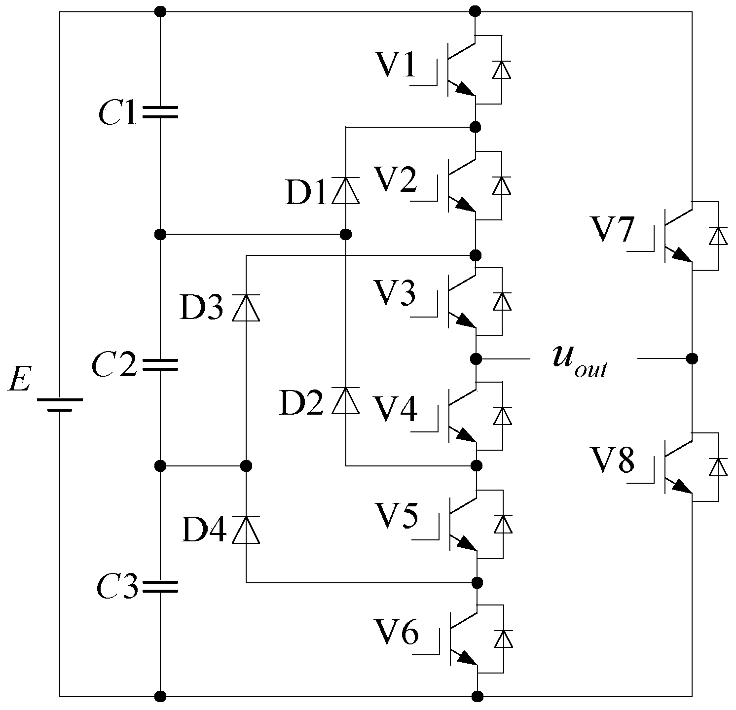
[0036] Specific implementation mode one: the following combination figure 1 and Figure 5 Describe this implementation mode, the method for eliminating zero-crossing distortion of the output voltage of the single-phase asymmetrical seven-level inverter described in this implementation mode, the single-phase asymmetrical seven-level inverter is as follows figure 1 As shown, it includes DC power supply E, capacitor C1, capacitor C2, capacitor C3, power switch tube V1, power switch tube V2, power switch tube V3, power switch tube V4, power switch tube V5, power switch tube V6, power switch Tube V7, power switch tube V8, diode D1, diode D2, diode D3 and diode D4;
[0037] The positive pole of the DC power supply E is simultaneously connected to one end of the capacitor C1, the power input end of the power switch tube V1, and the power input end of the power switch tube V7;
[0038] After the capacitor C1, the capacitor C2 and the capacitor C3 are connected in series in sequence,...
specific Embodiment approach 2
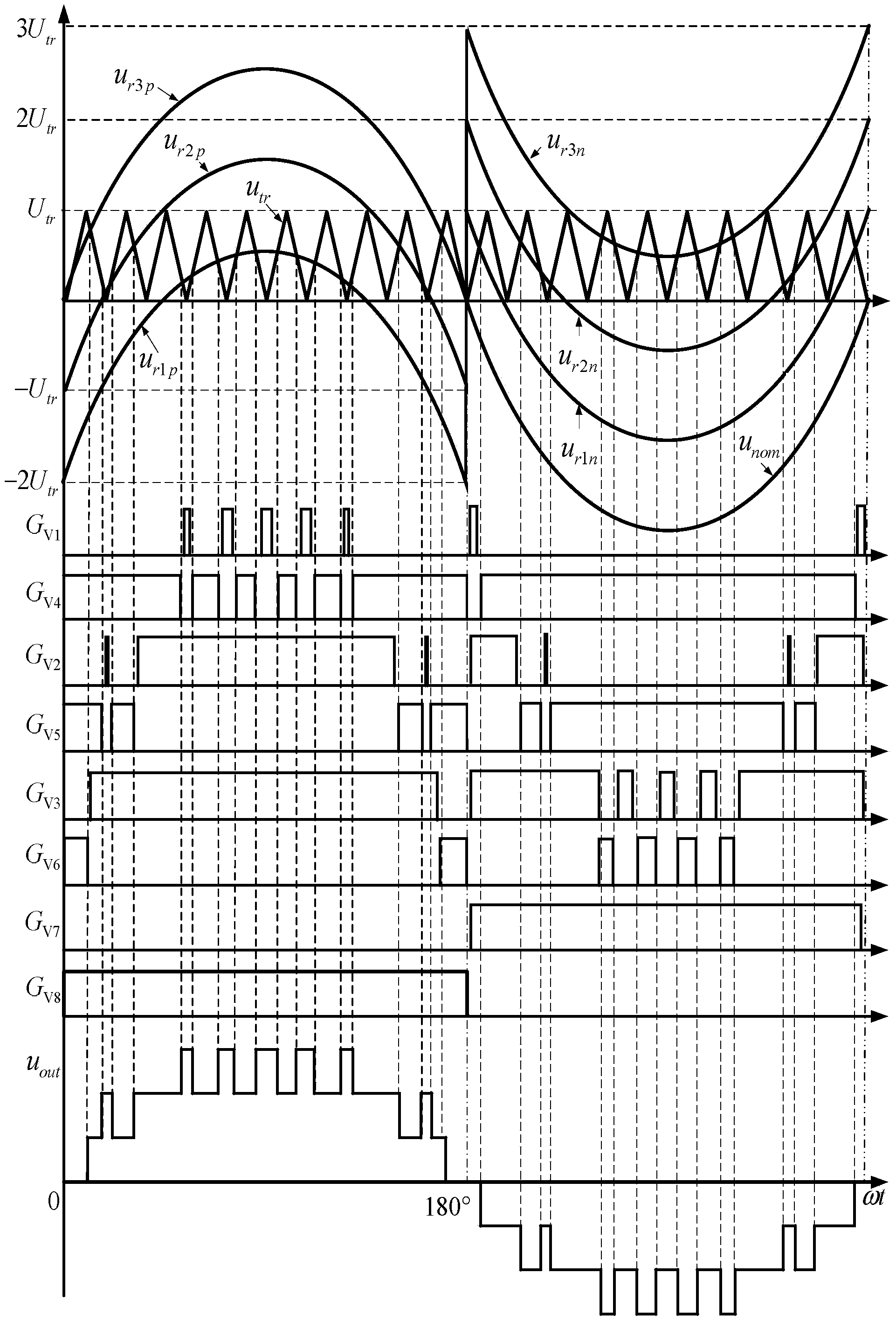
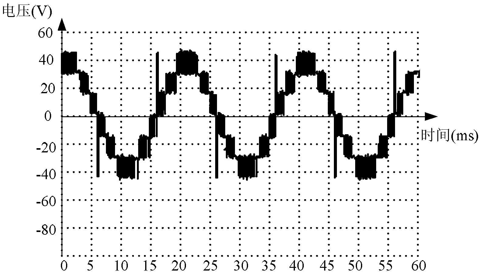
[0055] Specific implementation mode two: the following combination Figure 2 to Figure 4 , Figure 6 to Figure 8 Describe this implementation mode. This implementation mode will further explain the implementation mode 1. The multi-level modulation strategy is to use three modulation waves u r1 , u r2 , u r3 Compared with a triangular carrier wave, the comparison results are used as the control signals of the power switch tubes V1~V6 respectively,
[0056] modulation wave u r1 Positive half cycle u r1p =U nom sin(ω s t)-2U tr ;
[0057] Among them, U nom is the amplitude of the sine wave, ω s is the angular frequency of the sine wave, U tr is the amplitude of the triangular carrier wave;
[0058] modulation wave u r1 Negative half cycle u r1n =U tr + U nom sin(ω s t);
[0059] modulation wave u r2 Positive half cycle u r2p =U nom sin(ω s t)-U tr ;
[0060] modulation wave u r2 Negative half cycle u r2n =2U tr + U nom sin(ω s t);
[0061] modulation...
PUM
 Abstract
Description
Claims
Application Information
 - R&D
- Intellectual Property
- Life Sciences
- Materials
- Tech Scout
- Unparalleled Data Quality
- Higher Quality Content
- 60% Fewer Hallucinations
Browse by: Latest US Patents, China's latest patents, Technical Efficacy Thesaurus, Application Domain, Technology Topic, Popular Technical Reports.
© 2025 PatSnap. All rights reserved.Legal|Privacy policy|Modern Slavery Act Transparency Statement|Sitemap|About US| Contact US: help@patsnap.com


