
A chemical solution separation tank

A separation tank and solution technology, applied in the direction of liquid separation, liquid separation auxiliary equipment, separation methods, etc., can solve the problems of difficult measurement and control of buoyancy, unrealizable, unstable liquid level, etc., to achieve controllable processing speed and reduce turbulence Effect

Active Publication Date: 2022-07-29
山东龙华生物股份有限公司
View PDF11 Cites 0 Cited by
  • Summary
  • Abstract
  • Description
  • Claims
  • Application Information

AI Technical Summary

Problems solved by technology

However, based on the existing technology, there are still the following defects: 1. This method of separating different densities is limited to the method of visually observing the separation boundary, that is, it is necessary to exclude the situation of visual floating when entering the separation and discharging, and for multi-layer insoluble oil The separation between liquids, because the buoyancy of the wooden board as the boundary of different liquids is difficult to measure and control between different solutions, mostly for a variety of different immiscible liquids, this method is completely impossible to achieve;
[0004] 2. For the separation and recovery of various immiscible liquids, through the participation of external pressurization and other equipment, or when the pre-recovery liquid is replaced and recovered by filling the solution, the filled liquid will disturb or stir the pre-recovery liquid Due to the situation, the liquid level is unstable when the pre-recovery liquid is recovered, especially the recovery between the stratified critical layer position of different solutions, the recovery is difficult

Method used


Image

  • A chemical solution separation tank
  • A chemical solution separation tank
  • A chemical solution separation tank

Examples


Embodiment Construction

[0036] The technical solutions in the embodiments of the present invention will be clearly and completely described below with reference to the accompanying drawings in the embodiments of the present invention. Obviously, the described embodiments are only a part of the embodiments of the present invention, but not all of the embodiments. Based on the embodiments of the present invention, all other embodiments obtained by those of ordinary skill in the art without creative efforts shall fall within the protection scope of the present invention.

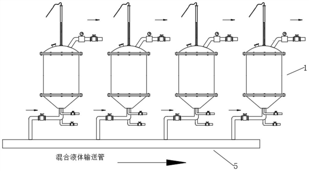
[0037] The present invention provides a technical solution: a chemical solution separation tank, comprising a treatment tank body 1 arranged in an arrangement and a mixed liquid conveying pipe 5 for centrally separating and conveying chemically mixed immiscible transparent liquids. The mixed liquid conveying pipe 5 transports Centralized delivery of mixed liquids, such as figure 1 As shown in the figure, the arrangement of the treatme...


PUM


Abstract

The invention discloses a chemical solution separation tank in the field of chemical separation technology. Layer composition, the layered critical layers of different densities of transparent liquids are respectively detected, the tank body of the treatment tank is provided with an oil filling mechanism at the bottom, and the oil filling mechanism includes an upper flow guide cover and a lower flow guide cover. , a retarding chamber is formed between the upper diversion cover body and the lower flow diversion cover body, each separate treatment tank of the present invention is separated and processed separately, and its processing speed is controllable, and the stratification is obtained through the stratification detection mechanism. The specific position of the stratified solution is measured, and the volume of a number of different stratified solutions in the separation tank is measured, and the oil filling mechanism is used to avoid affecting the stability of the stratified liquid level of the recovered liquid after stratification.

Description

technical field [0001] The invention relates to the technical field of chemical separation, in particular to a chemical solution separation tank. Background technique [0002] In chemical production, the mixture of different oils is inevitable in industrial production. The oils have different densities and their own characteristics, and can be separated when the mixing time is long, but different types of oils need to be classified and recycled. In the transparent solution with no color difference, it is difficult to use the control method to determine the stratification position between the solutions, and it is difficult to separate the liquids with insoluble and incompatible liquids with obvious differences such as boiling points, and it is even more difficult to operate. [0003] For example, Publication No. CN111790181A is a device for separating oil and water by density, including an oil-liquid separator main body, a motor is fixedly installed at the bottom of the oil-l...

Claims


Application Information

Patent Timeline
Patent Type & Authority Patents(China)
IPC IPC(8): B01D17/032B01D17/12
CPCB01D17/0214B01D17/12
Inventor 张田田
Owner 山东龙华生物股份有限公司
Learn More