Environment-friendly dust removal equipment for plant

A kind of dust removal equipment and environmental protection technology, which is applied in the direction of using liquid separating agent, fixed filter element filter, combined device, etc., can solve the problems of unusable, too much dust absorbed by the vacuum cleaner, and a lot of dust, so as to achieve the effect of ensuring the removal rate

Inactive Publication Date: 2021-07-09
肖海平
View PDF0 Cites 0 Cited by
  • Summary
  • Abstract
  • Description
  • Claims
  • Application Information

AI Technical Summary

Problems solved by technology

[0003] Various cutting or grinding operations will be carried out inside the factory building, and a large amount of dust will be generated during processing. The dust will have a serious impact on the health of workers. The existing factory building uses vacuum cleaners to remove dust. However, cutting during dust removal Or the dust generated at the grinding position is particularly large, and the dust absorption efficiency of the vacuum cleaner is affected. At the same time, it is easy to cause the vacuum cleaner to absorb too much dust and make it unusable. In addition, the dust removal effect is better for the dust located in the lower part of the factory building, while the dust that floats upward Dust cannot be removed well

Method used


Image

  • Environment-friendly dust removal equipment for plant
  • Environment-friendly dust removal equipment for plant
  • Environment-friendly dust removal equipment for plant

Examples


Embodiment Construction

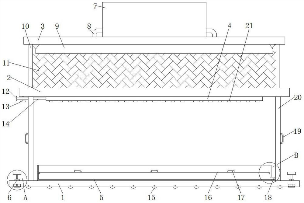
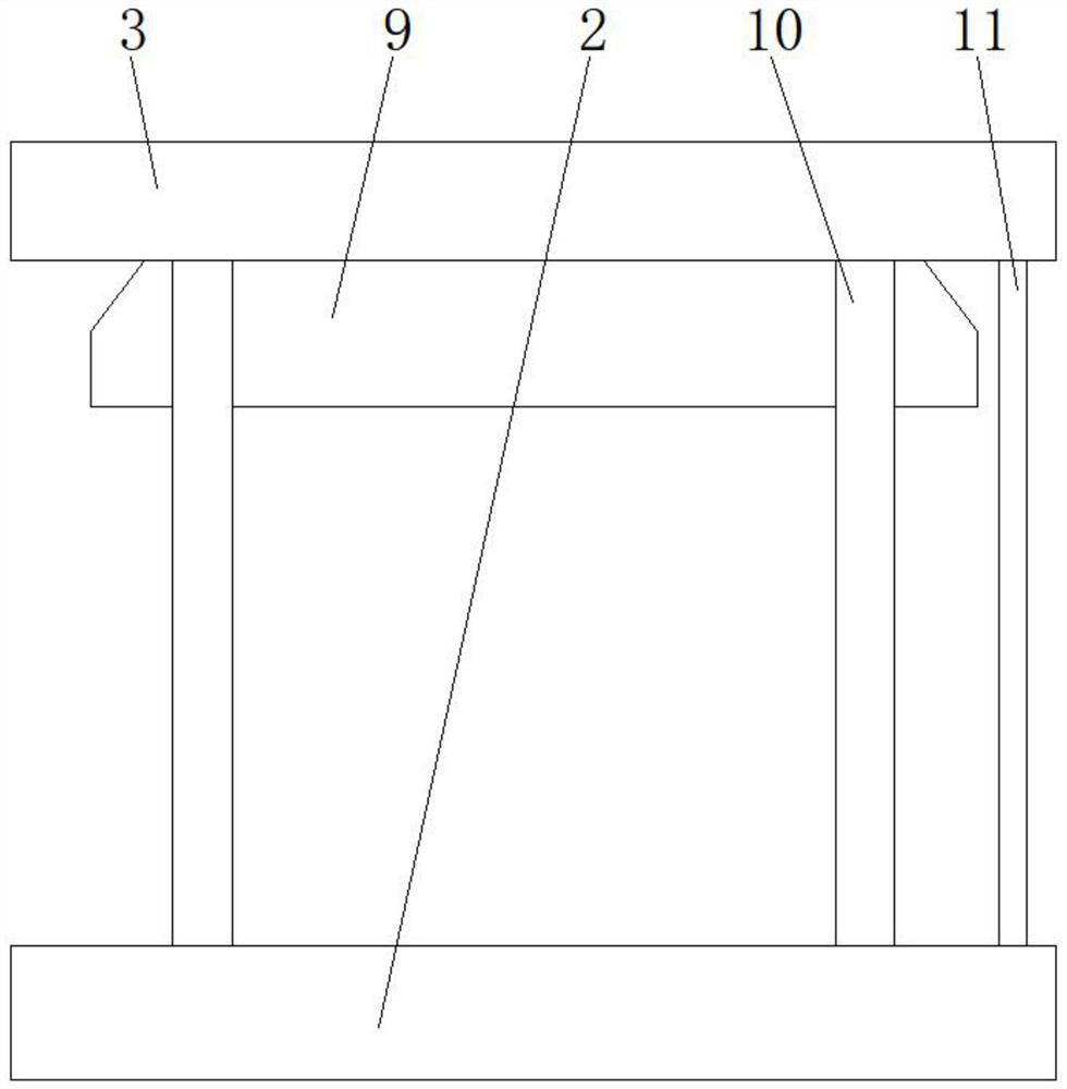
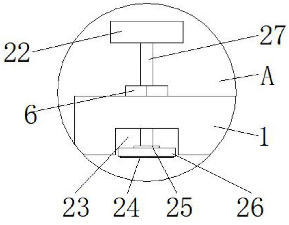
[0028] In order to make the technical means, creative features, goals and effects achieved by the present invention easy to understand, the present invention will be further described below in conjunction with specific embodiments.

[0029] In describing the present invention, it should be understood that the terms "upper", "lower", "front", "rear", "left", "right", "top", "bottom", "inner", " The orientation or positional relationship indicated by "outside", etc. is based on the orientation or positional relationship shown in the drawings, and is only for the convenience of describing the present invention and simplifying the description, rather than indicating or implying that the referred device or element must have a specific orientation, so as to Specific orientation configurations and operations, therefore, are not to be construed as limitations on the invention.

[0030] In the description of the present invention, it should be noted that, unless otherwise specified and...


PUM


Abstract

The invention relates to the technical field of environment-friendly dust removal, and discloses environment-friendly dust removal equipment for a plant. The equipment comprises a base, a transverse plate, a support plate, a spray pipe, a water receiving tank and a nut, the transverse plate is supported and fixed to the upper portion of the base through the supporting columns, the two supporting columns are fixed to the two sides of the lower portion of the transverse plate, the supporting plate is supported and fixed to the upper portion of the transverse plate through the supporting rods, the two supporting rods are fixed to the two sides of the lower portion of the supporting plate, the transverse plate and the supporting plate are both parallel to the base, the supporting columns support the two sides of the surface of the base, and the supporting rods support the two sides of the surface of the transverse plate. By arranging the transverse plate and the supporting plate and fixing the spraying pipe with the multiple spraying heads below the transverse plate, after the device is arranged at a designated position, most of dust generated during work can be cleaned away through water curtains sprayed out of the spraying heads, and then the dust scattered upwards is absorbed by an industrial dust collector through a dust collection cover; the dust removal rate is guaranteed, and meanwhile the dust removal effect of the dust collector is prevented from being affected by excessive dust.

Description

technical field [0001] The invention relates to the technical field of environmental protection dust removal, in particular to an environmental protection dust removal equipment for a factory building. Background technique [0002] At present, industrial plants refer to various houses that are directly used for production or supporting production, including main workshops, auxiliary buildings and auxiliary facilities. Plants should be included. In addition to workshops used for production, industrial plants also include their auxiliary buildings. Industrial plants can be divided into single-story industrial buildings and multi-storey industrial buildings according to their architectural structure. [0003] Various cutting or grinding operations will be carried out inside the factory building, and a large amount of dust will be generated during processing. The dust will have a serious impact on the health of workers. The existing factory building uses vacuum cleaners to remov...

Claims


Application Information

Patent Timeline
Patent Type & Authority Applications(China)
IPC IPC(8): B01D47/06B01D29/01B01D29/96B01D50/00
CPCB01D47/06B01D29/01B01D29/96B01D50/60
Inventor 肖海平
Owner 肖海平
Why Eureka
Try Eureka