
Insulator cleaning device and cleaning method

A cleaning device and technology for insulators, applied to chemical instruments and methods, cleaning methods and utensils, cleaning methods using liquids, etc., can solve the problems of cleaning insulators and other problems, and achieve the effect of convenience

Pending Publication Date: 2021-07-09
CRRC DALIAN R & D CO LTD
View PDF6 Cites 0 Cited by
  • Summary
  • Abstract
  • Description
  • Claims
  • Application Information

AI Technical Summary

Problems solved by technology

[0004] The above cleaning method can only be carried out when the EMU is stopped and the power is cut off. It cannot be found that the insulator is polluted in time when the EMU is running, and the insulator can be cleaned before the pollution flashover occurs.

Method used


Image

  • Insulator cleaning device and cleaning method
  • Insulator cleaning device and cleaning method
  • Insulator cleaning device and cleaning method

Examples


Embodiment 1

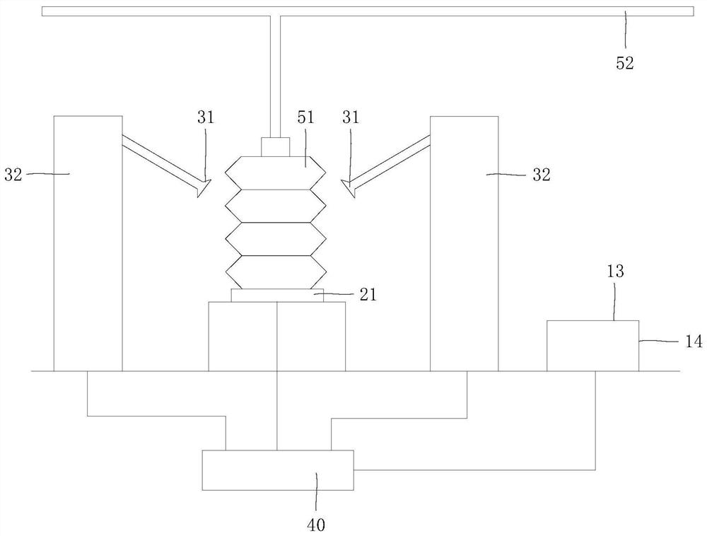
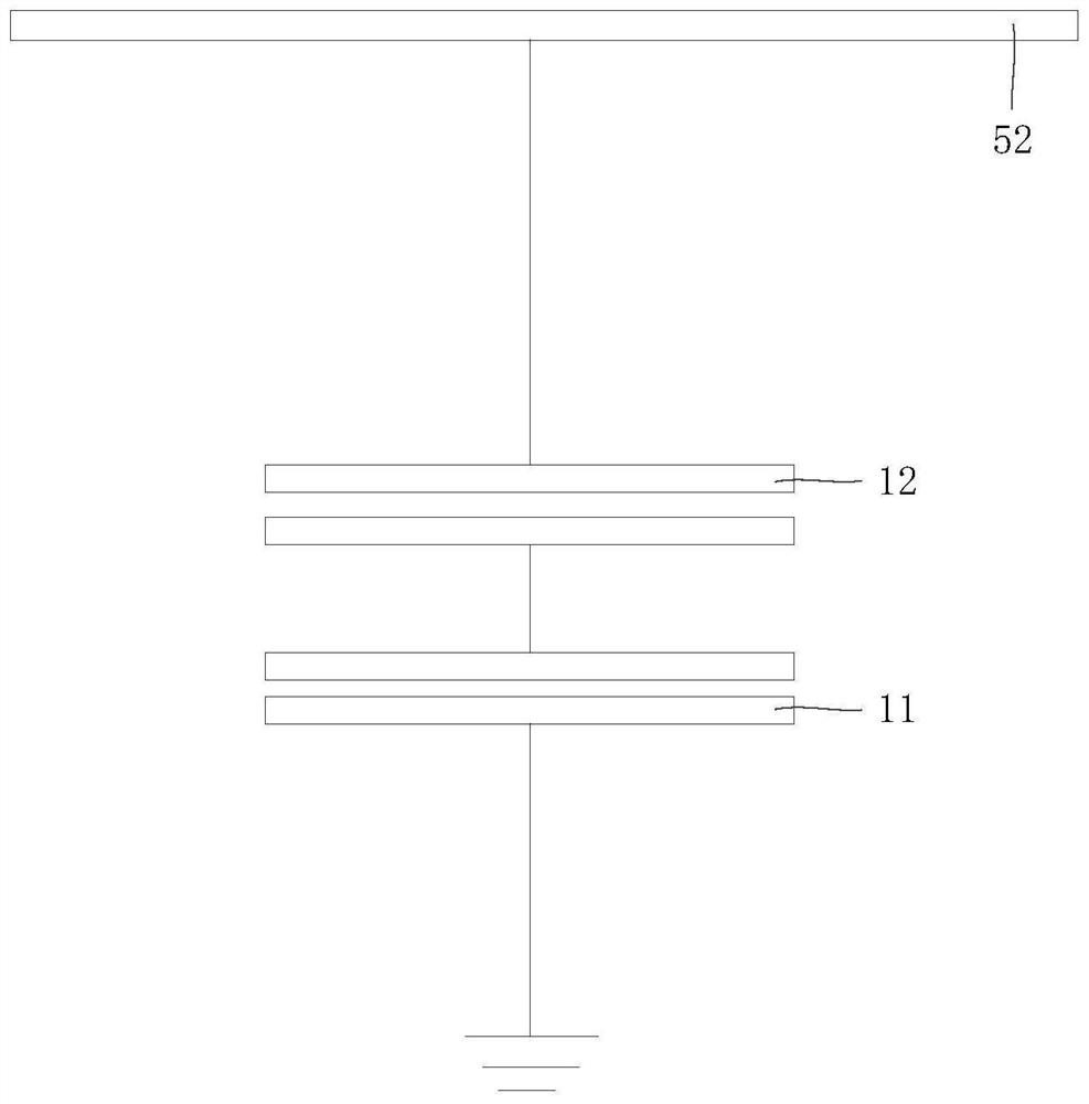
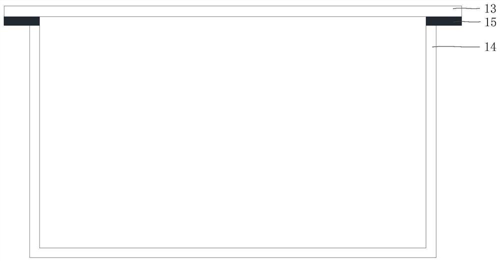
[0039] In order to solve the above problems, figure 1 It is a schematic structural diagram of an insulator cleaning device provided in Embodiment 1 of the present invention, figure 2 for figure 1 Schematic diagram of the structure of the induction plate and the shielding shell, image 3 For the schematic diagram of the voltage divider circuit, please refer to Figure 1 to Figure 3 , the present embodiment provides an insulator cleaning device, which includes a sampling assembly, a cleaning assembly and a controller 40; the sampling assembly includes a voltage sampling part and a current sampling part, the voltage sampling part is used to monitor the voltage of the catenary 52, and the current sampling part is used for To monitor the current passing through the insulator 51; the controller 40 is connected to the voltage sampling part and the current sampling part respectively, and the controller 40 obtains the voltage value measured by the voltage sampling part and the curre...

Embodiment 2

[0077] Figure 4For the schematic flow chart of the cleaning method provided by Embodiment 2 of the present invention, please refer to Figure 4 , this embodiment provides a cleaning method, which is applied to the insulator cleaning device of the first embodiment, including: the voltage sampling part measures the voltage value of the catenary 52, and the current sampling part measures the current value passing through the insulator 51; the controller 40 Obtain the current value and the voltage value; when the controller 40 determines that the voltage value is within the preset voltage range and the current value is greater than the preset current value, the controller 40 controls the cleaning component to clean the insulator.

[0078] It can be understood that the controller may include an analog input module, a processor module, an output module and a man-machine interface. The analog input module collects the voltage across the first capacitor 11 and the voltage across the...


PUM


Abstract

The invention provides an insulator cleaning device and a cleaning method. The insulator cleaning device comprises a sampling assembly, a cleaning assembly and a controller. The sampling assembly comprises a voltage sampling piece and a current sampling piece, the voltage sampling piece is used for monitoring the voltage of a contact network, and the current sampling piece is used for monitoring the current passing through an insulator. The controller is connected with the voltage sampling piece and the current sampling piece, and obtains a voltage value measured by the voltage sampling piece and a current value measured by the current sampling piece. When the voltage value is within a preset voltage range and the current value is greater than a preset current value, the controller controls the cleaning assembly to clean the insulator. The insulator cleaning device provided by the embodiment can monitor the pollution degree of the insulator in the running process of a motor train unit and can clean the insulator in time before pollution flashover of the insulator occurs.

Description

technical field [0001] The embodiments of the present invention relate to the technical field of electric locomotives, in particular to an insulator cleaning device and a cleaning method. Background technique [0002] The locomotive top insulator is installed between the roof and the pantograph bracket of the catenary, and is an important high-voltage insulation support part of the roof, which ensures the normal current receiving of the pantograph and also ensures that there is a gap between the pantograph and the roof of the train. Sufficient insulation distance. [0003] If the insulator is exposed to the air for a long time, dirt such as dust will adhere to its surface. When the pollution is in a state of infiltration, the insulator will have a flashover breakdown, that is, a pollution flashover fault. In order to avoid pollution flashover of insulators, offline cleaning methods are usually used in the prior art, that is, the locomotive is parked in the garage, the caten...

Claims


Application Information

Patent Timeline
Patent Type & Authority Applications(China)
IPC IPC(8): B08B3/12B08B13/00G01R19/165G01R31/52
CPCB08B3/12B08B3/024B08B13/00G01R19/16571G01R19/16576
Inventor 尹国龙孙佳伟姜涛吕雁文葛艳华
Owner CRRC DALIAN R & D CO LTD
Learn More