Working method of workpiece conveying and assembling equipment

A technology for assembling equipment and working methods, which is applied in metal processing equipment, assembly machines, metal processing, etc., and can solve problems that affect the smooth and orderly assembly process of U-shaped workpieces in the subsequent transfer, difficult U-shaped workpieces, directional sorting and transmission, and troublesome operations, etc. question

Inactive Publication Date: 2021-07-09
于金亚
View PDF0 Cites 8 Cited by
  • Summary
  • Abstract
  • Description
  • Claims
  • Application Information

AI Technical Summary

Problems solved by technology

Disk cover workpieces and U-shaped workpieces are commonly used workpieces now. Bearing end covers are commonly used disk cover workpieces. In order to facilitate the actual installation and use of disk cover workpieces, it is necessary to The U-shaped workpiece is connected and assembled with the plate-like workpiece. During the assembly process of the existing U-shaped workpiece and the plate-shaped workpiece, it is necessary to use a workpiece transfer device to transmit the U-shaped workpiece and the plate-shaped workpiece. The existing U-shaped workpiece In the process of conveying the two kinds of workpieces separately by the workpiece conveying device and the disk cover workpiece conveying device, it is difficult to realize that the two workpieces are transmitted synchronously with the same transmission rhythm, so that the two workpieces cannot be efficiently and smoothly conveyed one by one and guided smoothly and accurately. Press-fitting processing, the existing assembly processing of U-shaped workpieces and disc cover-type workpieces is mainly carried out manually, the automation degree of workpiece assembly processing is low, and it is difficult to meet the large-scale continuous processing of workpiece assembly. , U-shaped workpieces need to be transmitted continuously and smoothly in sequence. During the transmission process of U-shaped workpieces, in order to facilitate the continuous production and processing of workpieces in the subsequent process, it is necessary to orientate the U-shaped workpieces during the transmission process, so that The opening orientation of U-shaped workpieces can be kept consistent after sorting. The existing U-shaped workpiece sorting mechanism has a complicated structure and troublesome operation. Due to the special shape and structure of some U-shaped workpieces, it is difficult to realize the material-guiding transmission of U-shaped workpieces one by one during the transmission process, which affects the smooth and orderly progress of the subsequent transfer and assembly process of U-shaped workpieces. During the assembly and processing of workpieces, due to the circular structure of the disc cover workpiece, the disc cover workpiece is prone to rotation deviation during the material guide transmission, making it difficult for the U-shaped workpiece to be assembled with the upper side of the disc cover workpiece. Accurate and smooth press-fit connection of the groove requires adjusting the assembly station of the U-shaped workpiece or the disc-covered workpiece during the assembly process of the U-shaped workpiece or the disc-covered workpiece to achieve accurate assembly of the two workpieces. The position adjustment mechanism is complicated in structure and cumbersome to operate. It is difficult to adjust the workpiece position synchronously during the workpiece press-fitting process, which affects the efficiency and quality of workpiece assembly and processing, and cannot meet the needs of processing and use.

Method used


Image

  • Working method of workpiece conveying and assembling equipment
  • Working method of workpiece conveying and assembling equipment
  • Working method of workpiece conveying and assembling equipment

Examples


Embodiment Construction

[0019] In order to further describe the present invention, a specific implementation of a workpiece conveying and assembling device will be further described below in conjunction with the accompanying drawings. The following examples are explanations of the present invention and the present invention is not limited to the following examples.

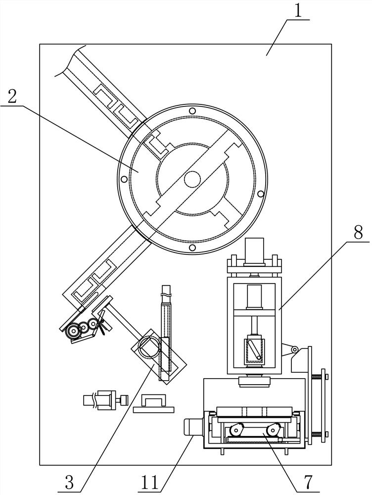
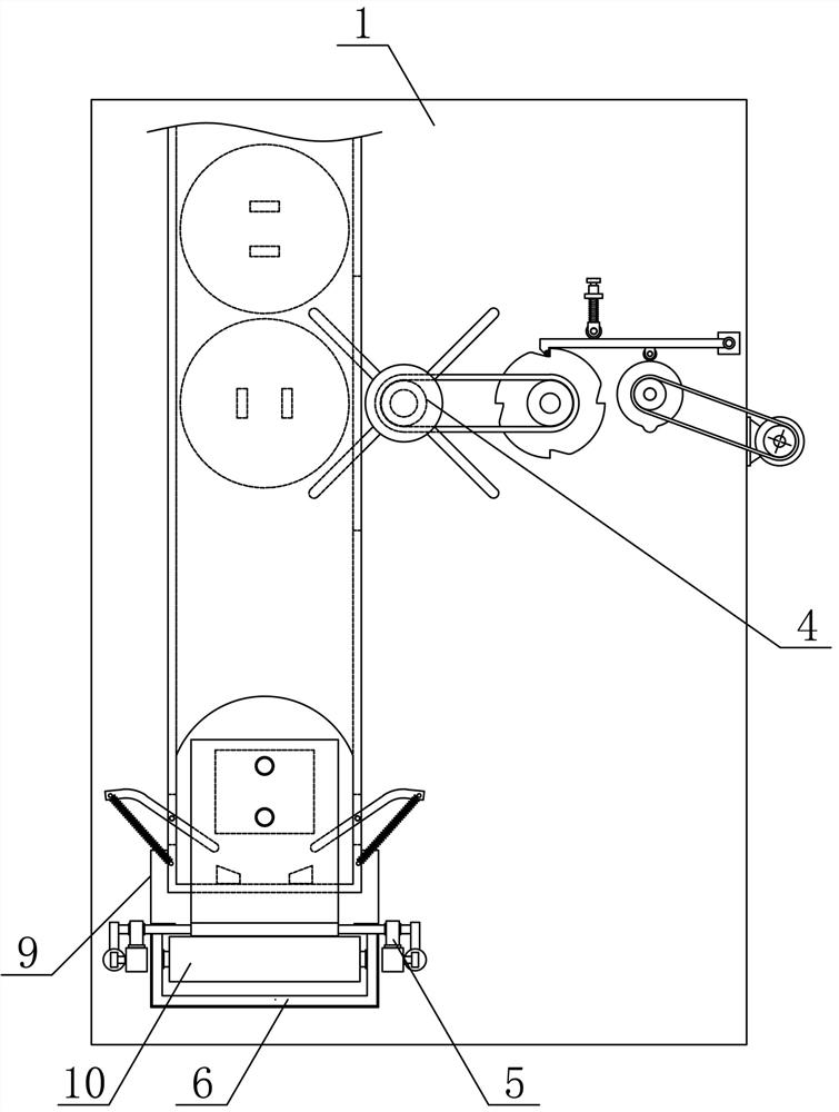
[0020] Such as figure 1 and figure 2 As shown, a workpiece conveying and assembling device of the present invention includes a workpiece assembly support 1, a U-shaped workpiece guide mechanism 2, a U-shaped workpiece transfer mechanism 3, a disc cover workpiece blanking mechanism 4, a disc cover workpiece transfer mechanism 5, and a disc cover workpiece transfer mechanism 5. The cover workpiece transmission bracket 6, the disc cover workpiece support mechanism 7 and the workpiece assembly mechanism 8, the U-shaped workpiece guide mechanism 2 and the disc cover workpiece blanking mechanism 4 are respectively vertically arranged on both ...


PUM


Abstract

The invention discloses a working method of workpiece conveying and assembling equipment, and belongs to the field of workpiece machining mechanical equipment. A U-shaped workpiece guiding mechanism and a disc cover workpiece blanking mechanism are vertically arranged on the two sides of a workpiece assembling support respectively, a U-shaped workpiece transferring mechanism is arranged on the workpiece assembling support on the lower side of the U-shaped workpiece guiding mechanism, a disc cover workpiece transferring mechanism is arranged on the workpiece assembling support on one side below the disc cover workpiece blanking mechanism, a disc cover workpiece conveying support is horizontally and fixedly arranged in a disc cover workpiece conveying channel, a disc cover workpiece bearing mechanism is horizontally arranged on the disc cover workpiece conveying support on the lower side of a workpiece assembling mechanism, and a plurality of disc cover conveying guide rollers are sequentially and rotationally connected to the disc cover workpiece conveying support in the horizontal direction. The working method is reasonable in structural design, two kinds of workpieces can be efficiently and smoothly conveyed and guided one by one, the two workpieces can be stably and accurately pressed and machined, the workpiece assembling automation degree is improved, and the machining and using requirements are met.

Description

technical field [0001] The invention belongs to the field of workpiece processing machinery and equipment, and in particular relates to a working method of workpiece conveying and assembling equipment, which is mainly applied to the field of continuous conveying and assembling processing of two kinds of workpieces. Background technique [0002] Mechanical workpieces are single parts that make up machinery and machines that cannot be separated. It plays an important role in the automation industry. Mechanical workpieces include the connection of parts, supporting parts, lubricating lubrication systems and sealing parts. Components, components of the transmission system that transmits motion and energy, and there are many types of workpieces. According to the function and shape of the workpieces, they can be mainly divided into: shaft sleeve workpieces, disc cover workpieces, fork bracket workpieces and box body workpieces. Disk cover workpieces and U-shaped workpieces are com...

Claims


Application Information

Patent Timeline
Patent Type & Authority Applications(China)
IPC IPC(8): B23P21/00B23P19/027B23P19/00
CPCB23P19/001B23P19/002B23P19/007B23P19/027B23P21/004B65G47/14
Inventor 於金亚
Owner 于金亚
Why Eureka
Try Eureka