
Dustproof type hot runner temperature control box for injection mold

An injection mold and dust-proof technology, which is applied in the field of dust-proof hot runner temperature control box, can solve the problems of blocking the external heat dissipation of electrical components, achieve the effect of improving the cooling effect and accelerating the heat dissipation speed

Pending Publication Date: 2021-07-09
张昌森
View PDF4 Cites 0 Cited by
  • Summary
  • Abstract
  • Description
  • Claims
  • Application Information

AI Technical Summary

Problems solved by technology

However, in the injection molding workshop, frequent loading of materials is required, and a large amount of dust is often splashed when the raw materials fall. Components dissipate heat

Method used


Image

  • Dustproof type hot runner temperature control box for injection mold
  • Dustproof type hot runner temperature control box for injection mold
  • Dustproof type hot runner temperature control box for injection mold

Examples


Embodiment 1

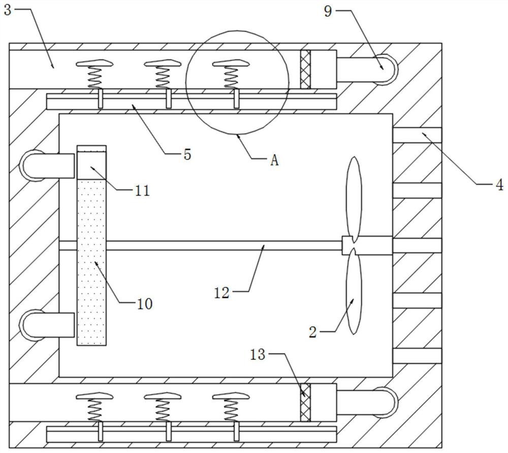
[0023] refer to Figure 1-2 , a dust-proof hot runner temperature control box for injection molds, including a box body 1, a cooling fan 2 is installed in the box body 1, it should be noted that the cooling fan 2 adopts an axial flow fan, so that the box body 1 The air flow inside is horizontal.

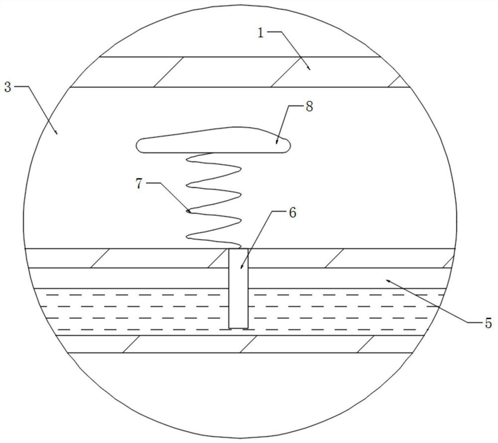
[0024] The upper and lower ends of the box body 1 are provided with air-introduction grooves 3, and the side walls of the box body 1 are provided with air outlets 4. The air-induction grooves 3 communicate with the inside of the box body 1 through copper pipes 9, and the air-induction grooves 3 are embedded with The filter screen 13, the filter screen 13 can block part of the volume of impurities and dirt, and prevent it from entering the inside of the box body 1 to form pollution. And the filter screen 13 is arranged on one side close to the air inlet end of the copper pipe 9 . A plurality of vibrating springs 7 are fixedly connected to the inner bottom of the air induction groove...

Embodiment 2

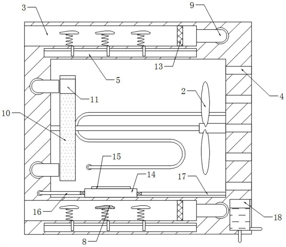
[0032] refer to image 3 , different from Embodiment 1, the bottom of the box body 1 is fixedly connected with an elastic cylinder 14, the side wall of the box body 1 is provided with a second liquid storage tank 18, and the elastic cylinder 14 communicates with the second liquid storage tank 18. The one-way liquid inlet pipe 16 and the one-way liquid outlet pipe 17, the one-way liquid inlet pipe 16 only allows the cooling liquid to flow from the second liquid storage tank 18 to the elastic cylinder 14, and the one-way liquid outlet pipe 17 only allows the cooling liquid to flow from the elastic cylinder 14 To flow to the second liquid storage tank 18, specifically, a check valve can be installed in the pipeline.

[0033] It should be noted that, if figure 2 As shown, the one-way liquid inlet pipe 16 is arranged in the box body 1 in a serpentine shape, which can increase the contact area with the electrical equipment in the box body 1, thereby increasing the heat dissipation...


PUM


Abstract

The invention discloses a dustproof type hot runner temperature control box for an injection mold. The dustproof type hot runner temperature control box comprises a box body, wherein a cooling fan is installed in the box body, air inducing grooves are formed in the upper end and the lower end of the box body, air outlets are formed in the side wall of the box body, and the air inducing grooves communicate with the interior of the box body through copper tubes; a plurality of vibration springs are fixedly connected to the bottoms in the air inducing grooves and wrapped with water absorption down, a first liquid storage groove is formed in the side wall of the box body and filled with water, a water absorption strip connected with the water absorption down is embedded in the top in the first liquid storage groove, and a vibration device enabling the vibration springs to vibrate is installed in the box body. The vibration springs are continuously vibrated, so that water can be smashed into a large number of liquid drops, and thus, the liquid drops and dust in air can form heavy condensation nuclei, the condensation nuclei cannot continuously flow along with airflow, dust removal and purification can be conducted on the air entering the temperature control box, and the situation that the dust enters the temperature control box, and consequently electrical equipment is damaged is prevented.

Description

technical field [0001] The invention relates to the technical field of injection mold-related equipment, in particular to a dust-proof hot runner temperature control box for injection molds. Background technique [0002] The hot runner temperature control box is an electrical device that controls the temperature of the hot runner of the mold. It is generally installed next to the injection molding machine that is easy to control. [0003] Since the mold will generate a lot of heat during the injection molding process, resulting in a higher temperature of the accessories of the temperature control box, so the temperature control box is generally equipped with a cooling fan for heat dissipation. However, in the injection molding workshop, frequent loading of materials is required, and a large amount of dust is often splashed when the raw materials fall. The components dissipate heat externally. In view of this, this application document proposes a dust-proof hot runner tempe...

Claims


Application Information

Patent Timeline
IPC IPC(8): B29C45/73B29C45/27
CPCB29C45/73B29C45/2737B29C2045/2753
Inventor 张昌森
Owner 张昌森
Features
  • Generate Ideas
  • Intellectual Property
  • Life Sciences
  • Materials
  • Tech Scout
  • Unparalleled Data Quality
  • Higher Quality Content
  • 60% Fewer Hallucinations
Learn More