Automatic cooling device for large shaft workpieces after quenching

An automatic cooling device and technology for shaft workpieces, applied in the field of quenching and cooling, can solve problems such as uneven cooling force, deformation and cracking of workpieces, and achieve the effects of reducing cost expenditure, uniform temperature drop, and improving pass rate

Pending Publication Date: 2021-07-09
祁永幸
View PDF5 Cites 2 Cited by
  • Summary
  • Abstract
  • Description
  • Claims
  • Application Information

AI Technical Summary

Problems solved by technology

[0003] In order to solve the above technical problems, an automatic cooling device for large-scale shaft workpieces after quenching is provided. This technical solution solves the problem of deformation and cracking of workpieces due to uneven cooling force, and the uniform temperature drop of workpieces is achieved through intermittent cooling of multiple components. , reduce the cost and increase the pass rate

Method used


Image

  • Automatic cooling device for large shaft workpieces after quenching
  • Automatic cooling device for large shaft workpieces after quenching
  • Automatic cooling device for large shaft workpieces after quenching

Examples


Embodiment Construction

[0045] The following description serves to disclose the present invention to enable those skilled in the art to carry out the present invention. The preferred embodiments described below are only examples, and those skilled in the art can devise other obvious variations.

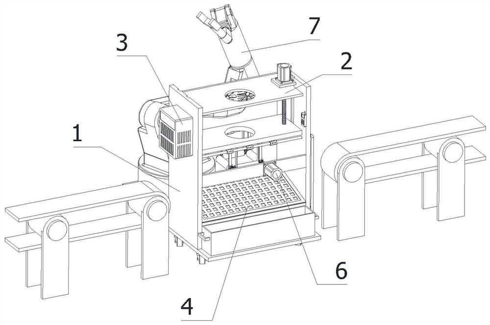
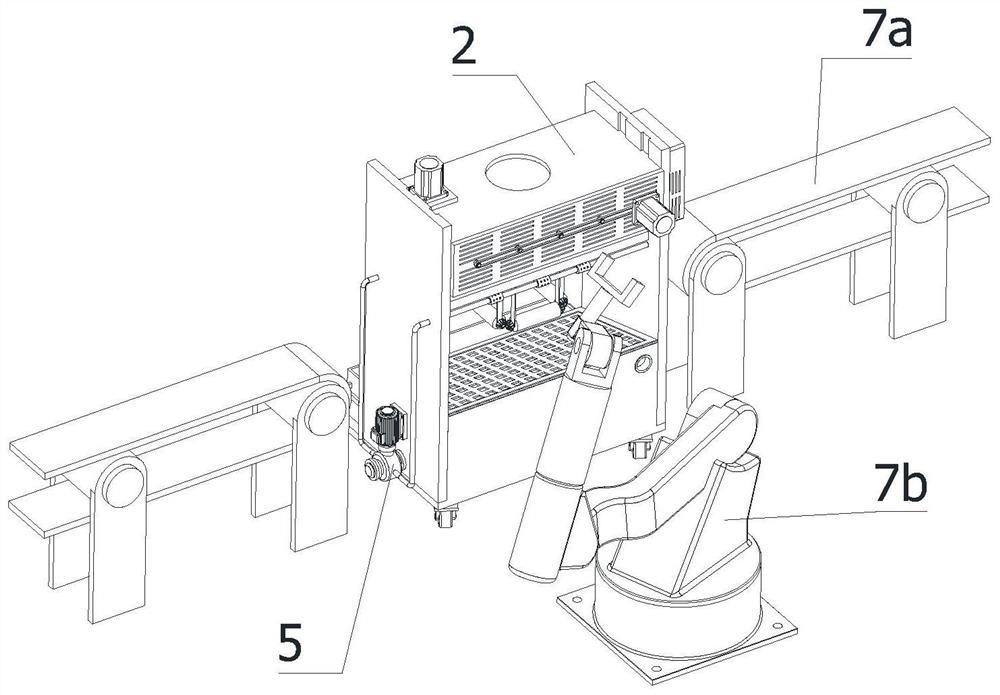
[0046] refer to Figure 1-2 As shown, an automatic cooling device for a large shaft workpiece after quenching, including:
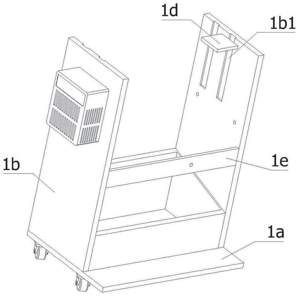
[0047] Rack 1;

[0048] Lifting assembly 2, the lifting assembly 2 is located at the top of the frame 1, and the lifting assembly 2 is used to drive the workpiece to rise and move down;

[0049] Cooling assembly 3, the cooling assembly 3 is located in the middle of the frame 1, the cooling assembly 3 is used to place the workpiece on the cooling assembly 3 through the lifting assembly 2, and the heat transfer cooling assembly 3 reduces the heat of the workpiece;

[0050] Brush head assembly 6, described brush head assembly 6 is positioned at the below of cooling assembly 3, and descr...


PUM


Abstract

The invention relates to the technical field of quenching cooling, in particular to an automatic cooling device for large shaft workpieces after quenching. The automatic cooling device comprises a rack, a lifting assembly, a cooling assembly, a brush head assembly, a spraying assembly, a filtering assembly and a material moving assembly, the workpieces are placed on the lifting assembly through the material moving assembly, and the lifting assembly drives the workpieces to be placed on the cooling assembly. The cooling assembly precools a workpiece, when the temperature is reduced to a set threshold value, the spraying assembly secondarily cools the workpiece and washes off oil stains on the workpiece, the brush head assembly cleanly scrubs off the oil stains on the workpiece, the oil stains scrubbed off by the brush head assembly are separated through the filtering assembly, and after the workpiece is scrubbed clean, the lifting assembly drives the workpiece to return to the top of the rack to take down the workpiece, through the operations, the problem that the workpiece is burnt out due to uneven cooling intensity is solved, through cooling of the multiple assemblies, the temperature of the workpiece is evenly reduced, the cost expenditure is reduced, and the percent of pass is increased.

Description

technical field [0001] The invention relates to the technical field of quenching and cooling, in particular to an automatic cooling device for large shaft workpieces after quenching. Background technique [0002] The quenching of steel is to heat the steel to a temperature above the critical temperature Ac3 (hypoeutectoid steel) or Ac1 (hypereutectoid steel), keep it warm for a period of time to make it fully or partially austenitized, and then cool it with a cooling rate greater than the critical cooling rate. The heat treatment process of rapidly cooling below Ms (or isothermal near Ms) for martensite (or bainite) transformation. To make austenite in steel transform into martensite during cooling, the cooling rate must be greater than that of steel. Critical cooling rate, during the cooling process of the workpiece, there is a certain difference in the cooling rate between the surface and the core. If this difference is large enough, it may cause the part greater than the ...

Claims


Application Information

Patent Timeline
Patent Type & Authority Applications(China)
IPC IPC(8): C21D1/62C21D1/667C21D9/28B08B1/04B08B3/02
CPCC21D1/62C21D1/667C21D9/0062C21D9/28B08B3/02B08B1/002B08B1/04
Inventor 祁永幸
Owner 祁永幸
Why Eureka
Try Eureka