A vortex chamber inlet structure of a swirling flood discharge tunnel for improving water flow

A technology of flood discharge tunnels and vortex chambers, which is applied in water conservancy projects, hydroelectric power generation, hydropower stations, etc., can solve the problems of insufficient energy dissipation in the downstream, large rise height of vortex chamber water flow, etc., to reduce water surface climbing and improve water flow state, the effect of reducing the height difference of the water surface

Active Publication Date: 2022-07-22
POWERCHINA XIBEI ENG +1
View PDF3 Cites 0 Cited by
  • Summary
  • Abstract
  • Description
  • Claims
  • Application Information

AI Technical Summary

Problems solved by technology

[0004] In order to overcome the existing problems of complex water flow state, large rising height of vortex chamber water flow and insufficient downstream energy dissipation, the present invention provides a vortex chamber inlet structure of swirl flood discharge tunnel that improves water flow state. The height of the vortex chamber ensures the safe operation of the flood tunnel with high water head and large flow, and the construction is convenient

Method used


Image

  • A vortex chamber inlet structure of a swirling flood discharge tunnel for improving water flow
  • A vortex chamber inlet structure of a swirling flood discharge tunnel for improving water flow

Examples


Embodiment 1

[0021] In order to overcome the problems that the existing water flow is complicated, the water flow in the vortex chamber has a large rising height, and the downstream energy dissipation is insufficient, the present invention provides such as Figure 1-2 As shown in the vortex chamber inlet structure of the swirl flood discharge tunnel for improving the water flow state, the invention reduces the height of the vortex chamber, ensures the safe operation of the flood discharge tunnel with high head and large flow, and is convenient for construction.

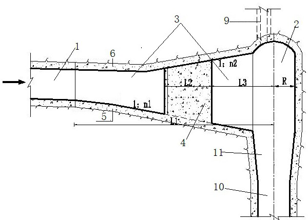
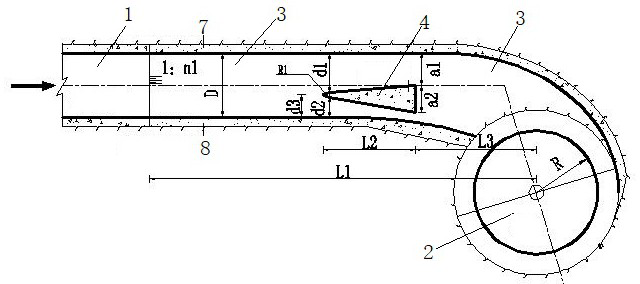
[0022] A vortex chamber inlet structure of a swirling flood discharge tunnel for improving water flow state, comprising a water diversion tunnel 1 and a vortex chamber 2, a transition section 3 and a water dividing wall 4, and the transition section 3 is from the diversion tunnel 1 to the vortex chamber. 2, the water dividing wall 4 is arranged on the transition section 3.

[0023] In the present invention, the transition section ...

Embodiment 2

[0026] Based on Embodiment 1, in this embodiment, preferably, the transition section 3 is composed of a bottom plate 5 , a side wall 7 , a side wall 2 8 and a top arch 6 . The second wall 8 is vertically arranged between the bottom plate 5 and the top arch 6, the bottom plate 5 is inclined, the side wall 7 is arranged on the side away from the vortex chamber 2, and the side wall 2 8 is arranged near the vortex chamber 2. side wall, the height of which is transitioned from the side wall of the diversion tunnel 1 to the wall height of the vortex chamber 2; The arc segments are connected with the side wall of the vortex chamber 2 . The section of the transition section 3 is horseshoe-shaped.

[0027] Preferably, the position of the bottom plate 5 in the water diversion tunnel 1 is higher than the position in the vortex chamber 2 .

[0028] Preferably, the slope ratio of the bottom plate 5 is 1:n1, n1 is 1~10, the distance between the starting point of the slope and the center l...

Embodiment 3

[0037] On the basis of Embodiment 1 or 2, in this embodiment, preferably, the thickness of the side wall 17 is 50cm; the width D of the bottom plate 5 is 700cm, the slope ratio of the bottom plate 5 is 1:5.7, and the slope ratio of the slope section of the top arch 6 is 1:3.5, the radius R of the vortex chamber 2 is 675cm, the distance a1 between the backwater surface and the side wall 7 of the transition section 3 is 350cm, the width a2 of the backwater surface is 300cm, the arc radius R1 of the waterfront surface is 150cm, and the sidewalls 1 and 7 of the waterfront surface are The distance between the first wall 7 is d1 is 430cm, the distance d2 between the side wall 2 and the side wall 2 8 is 220cm, the distance between the central axis of the upstream surface and the side wall 2 8 is d3 is 230 cm, the bottom plate 5 The distance between the slope point and the center line of the vortex chamber 2 is L1 is 4220cm, the length L2 of the water dividing wall 4 along the water fl...


PUM


Abstract

The invention provides a vortex chamber inlet structure of a swirling flood discharge tunnel for improving the flow state of water flow, which includes a water diversion tunnel and a vortex chamber, and also includes a transition section and a water dividing wall, and the transition section is the connection section between the diversion tunnel and the vortex chamber. , the water dividing wall is arranged on the transition section. The vortex chamber inlet structure of the whirlpool flood discharge tunnel provided by the invention improves the flow state of the water flow. When the water flows through the transition section and the water dividing wall, the thickness of the whirling water flow in the whirl chamber increases, the water surface climbs up greatly, and the water surface of the whirling water current in the whirl chamber is high. The difference is also reduced, which can improve the water flow pattern.

Description

technical field [0001] The invention belongs to the technical field of swirl energy dissipation in water conservancy and hydropower engineering, and particularly relates to a swirl flood discharge tunnel inlet structure for improving water flow state. Background technique [0002] To build a power station in the alpine and canyon areas, it is generally necessary to build several diversion tunnels. For the diversion tunnels with large investment, if they are only used during the construction of the dam, it is not economical. Therefore, the temporary building diversion tunnels are converted into permanent building flood discharge tunnels. It is a more economical solution, and the use of swirl energy dissipation technology is one of the important technologies for converting diversion tunnels into flood discharge tunnels. [0003] The working principle of swirl energy dissipation is to use the rotating motion of water flow to consume most of the water energy inside the flow chan...

Claims


Application Information

Patent Timeline
Patent Type & Authority Patents(China)
IPC IPC(8): E02B9/04
CPCE02B9/04Y02E10/20
Inventor 周恒尹进步陆希刘静丁新潮王卫国王凡李跃涛
Owner POWERCHINA XIBEI ENG
Why Eureka
Try Eureka