

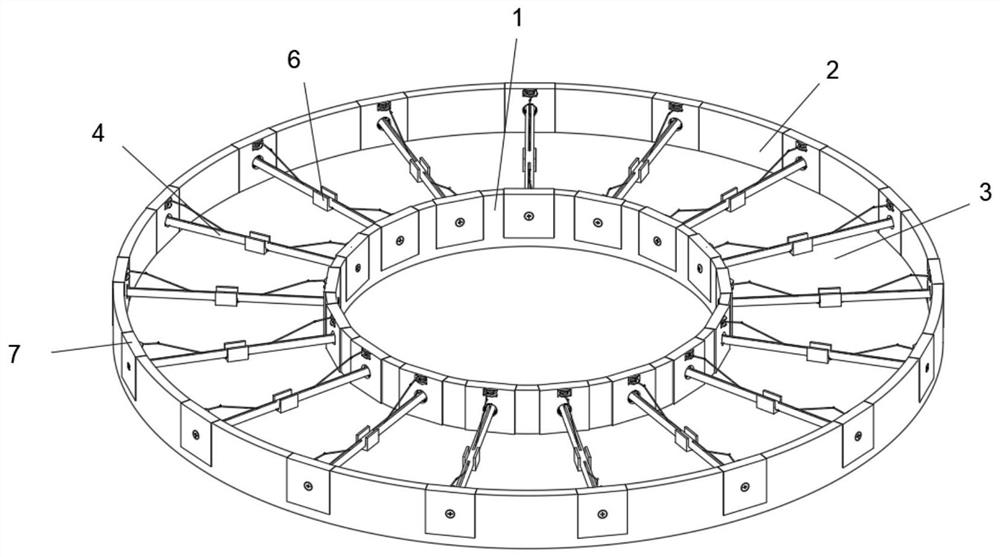
Carbon fiber cable reinforced spoke type cable truss structure
A carbon fiber and spoke-type technology, applied in the field of truss structures, can solve problems such as damage and unfavorable structural strength, and achieve the effects of increasing construction speed, convenient and fast installation, and improving connection strength
- Summary
- Abstract
- Description
- Claims
- Application Information
AI Technical Summary
Problems solved by technology
Method used
Image

Examples
Embodiment Construction
[0025] In describing the present invention, it is to be understood that the terms "center", "longitudinal", "transverse", "length", "width", "thickness", "upper", "lower", "front", " Orientation indicated by rear, left, right, vertical, horizontal, top, bottom, inside, outside, clockwise, counterclockwise, etc. The positional relationship is based on the orientation or positional relationship shown in the drawings, which is only for the convenience of describing the present invention and simplifying the description, rather than indicating or implying that the referred device or element must have a specific orientation, be constructed and operated in a specific orientation, Therefore, it should not be construed as limiting the invention.
[0026] In the description of the present invention, "plurality" means two or more, unless otherwise specifically defined.
[0027] In the description of the present invention, it should be noted that, unless otherwise specified and limited, ...
PUM
 Abstract
Description
Claims
Application Information