Safe vehicle locking method

A safety lock and card lock technology, applied in the field of locks, can solve problems such as safety hazards, throwing out, damage, etc., and achieve the effect of reducing safety hazards and preventing damage

Active Publication Date: 2021-07-09
HUIZHOU KINGLY MOTOR CO LTD
View PDF8 Cites 0 Cited by
  • Summary
  • Abstract
  • Description
  • Claims
  • Application Information

AI Technical Summary

Problems solved by technology

No matter what kind of lock it is, the locking process is the same, that is, the deadbolt will directly stop the wheel, and the most common is that the deadbolt passes from one side of the wheel to the other, thereby stopping the wheel from turning. , the biggest problem with this method of locking the car is that if it is suddenly locked during high-speed driving, the automatic car or electric car will suddenly stop moving, which will cause the user to be thrown out for a certain distance due to inertia and cause damage. There is a big security risk

Method used


Image

  • Safe vehicle locking method
  • Safe vehicle locking method
  • Safe vehicle locking method

Examples


Embodiment 1

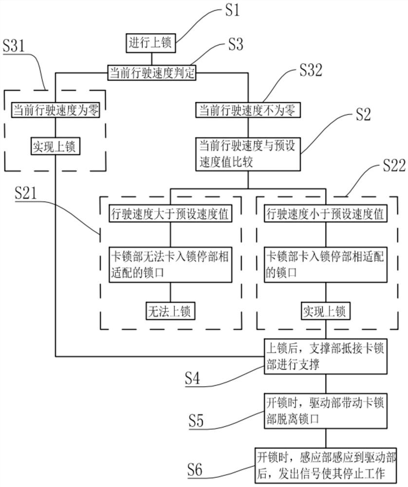
[0042] like figure 1 as shown, figure 1 It is a flow chart of the method for safely locking the car in Embodiment 1. A method for safely locking a car in this embodiment includes

[0043] S1: Perform a locking operation; the locking operation may be performed after receiving a locking instruction, or may be performed manually.

[0044] S2: compare the current driving speed with the preset speed value;

[0045] S21: If the current driving speed is greater than the preset speed value, the locking part 2 will not be able to snap into the locking opening 111 provided on the locking part 1 and matched with the locking part 2, so locking cannot be realized;

[0046] S22: If the current driving speed is lower than the preset speed value, the locking part 2 will be locked into the locking opening 111 provided on the locking part 1 and matched with the locking part 2 to realize locking.

[0047] It should be noted that the preset speed value in this embodiment is not a fixed value,...

Embodiment 2

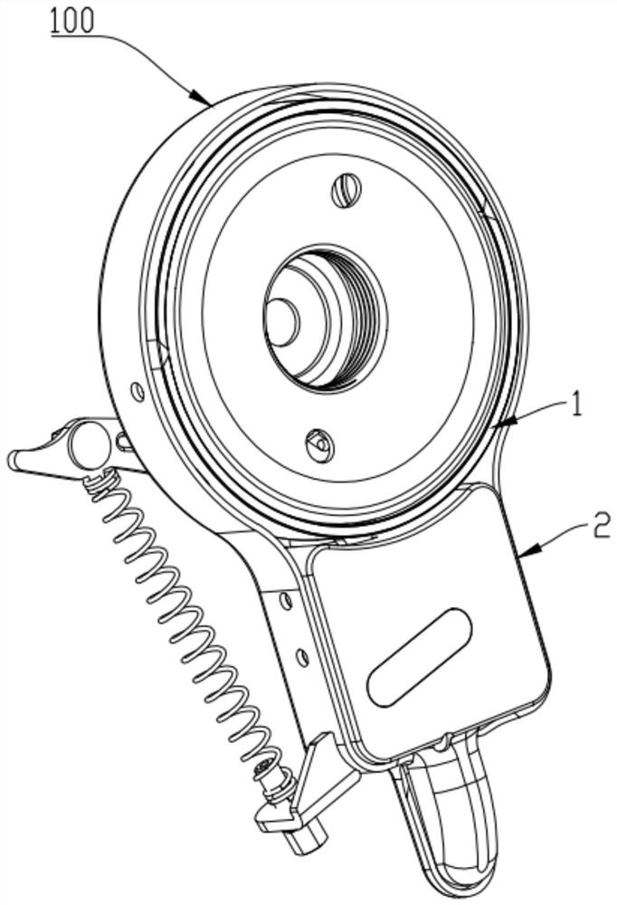
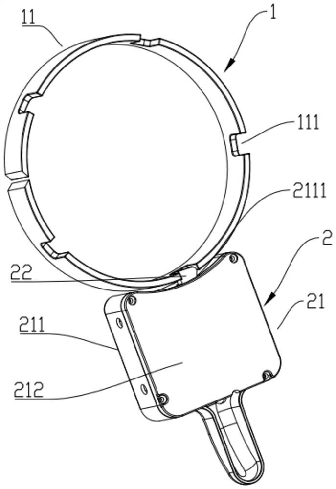
[0067] This embodiment is a specific structure for implementing the method mentioned in Embodiment 1. Of course, this is only one embodiment, and it is not limited to this one, and it can also be realized by other structures.

[0068] like Figure 2-Figure 4 as shown, figure 2 It is a schematic diagram of the use of the lock in Embodiment 2; image 3 It is a three-dimensional structure diagram of the lock in embodiment two; Figure 4 It is another three-dimensional structure diagram of the lock in the second embodiment. The locking part 1 includes a lock body 11 . The lock body 11 is inserted into the hub 100 and rotates together with the hub 100 . The lock opening 111 is opened on the lock body 11 . The locking part 2 includes a first carrier 21, a locking member 22 and a first elastic member 23, the first carrier 21 is arranged adjacent to the lock body 11, the locking member 22 is arranged on the first carrier 21, and the locking member 22 rotates Set on the first carr...

Embodiment 3

[0084] like Figure 10-Figure 12 as shown, Figure 10 It is the three-dimensional structure diagram of the third gear set 31223 in the third embodiment; Figure 11 It is the explosion schematic diagram of the third gear set 31223 in the third embodiment; Figure 12 It is another explosion schematic diagram of the third gear set 31223 in the third embodiment. The structure of this embodiment is similar to that of Embodiment 1, the difference is that the third gear set 31223 of this embodiment has a clutch function, and its specific structure is as follows:

[0085] Please also refer to Figure 4 and Figure 5 , the third gear set 31223 includes a wheel shaft 312231, a first sub-teeth 312232, a second sub-teeth 312233 and a third elastic member (not marked in the figure), the wheel shaft 312231 is rotatably set on the second carrier 311, and the first sub-teeth 312232 sets Set on the wheel shaft 312231, and the first sub-teeth 312232 mesh with the second gear set 31222; the...


PUM


Abstract

The invention discloses a safe vehicle locking method. The safe vehicle locking method comprises the following steps that the current running speed is compared with a preset speed value during locking; when the current running speed is larger than the preset speed value, a clamping and locking part cannot be clamped into a matched locking opening in a locking and stopping part, and locking cannot be conducted; and when the current running speed is smaller than the preset speed value, the clamping and locking part is clamped into the locking opening, and locking is achieved. The running speed is distinguished according to the preset speed value, when the running speed is larger than the preset value, if vehicle locking is needed, due to the fact that the speed is high, the clamping and locking part cannot be clamped into the locking opening, locking cannot be conducted, the locking and stopping part continues to run along with wheels, sudden locking in the rapid running process is avoided, hurt to a user is prevented, and the potential safety hazard is greatly reduced. If the running speed is smaller than the preset speed value, the clamping and locking part can be clamped into the locking opening, the locking and stopping part stops moving, then the wheels also stop moving, locking and stopping are achieved, and due to the fact that the running speed is low, the problem of the potential safety hazard does not exist.

Description

technical field [0001] The invention relates to the technical field of locks, in particular to a method for safely locking a car. Background technique [0002] Bicycles and electric vehicles are currently widely used means of transportation, which can not only meet people's short-distance needs, but also have a certain exercise effect; in order to prevent theft, locks are usually added to bicycles or electric vehicles. The current locks are mainly It can be divided into two categories, one is to lock manually, and the other is to lock through remote program control. No matter what kind of lock it is, the locking process is the same, that is, the deadbolt will directly stop the wheel, and the most common is that the deadbolt passes from one side of the wheel to the other, thereby stopping the wheel from turning. , the biggest problem with this method of locking the car is that if it is suddenly locked during high-speed driving, the automatic car or electric car will suddenly...

Claims


Application Information

Patent Timeline
IPC IPC(8): E05B71/00E05B47/00E05B15/00B62H5/18B62H5/14
CPCE05B71/00E05B47/0012E05B15/00B62H5/18B62H5/148E05B2047/0067
Inventor 钟梦超王小文
Owner HUIZHOU KINGLY MOTOR CO LTD
Why Eureka
Try Eureka