A Diesel Engine Four-Cylinder Crankshaft Preventing Vibration

A diesel engine and crankshaft technology, applied in crankshafts, engine components, engine lubrication, etc., can solve the problems of reducing the transmission accuracy of the four-cylinder crankshaft, affecting the service life of the four-cylinder crankshaft, increasing the jitter of the four-cylinder crankshaft, etc., to reduce the cylinder movement. Caton, improve kinetic energy transmission efficiency, reduce transmission wear effect

Active Publication Date: 2021-12-03
JIANGSU WANLI MACHINERY
View PDF0 Cites 0 Cited by
  • Summary
  • Abstract
  • Description
  • Claims
  • Application Information

AI Technical Summary

Problems solved by technology

Most of the existing four-cylinder crankshafts are in-line transmission. During the transmission process, due to the increase of stroke and cylinder diameter, the vibration of the four-cylinder crankshaft in the process of power transmission is also increasing, which reduces the transmission accuracy of the four-cylinder crankshaft. It is easy to cause the cylinder movement to be stuck, reduce work efficiency, and affect the service life of the four-cylinder crankshaft

Method used


Image

  • A Diesel Engine Four-Cylinder Crankshaft Preventing Vibration
  • A Diesel Engine Four-Cylinder Crankshaft Preventing Vibration
  • A Diesel Engine Four-Cylinder Crankshaft Preventing Vibration

Examples


Embodiment 1

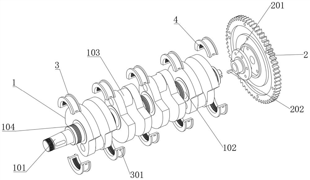
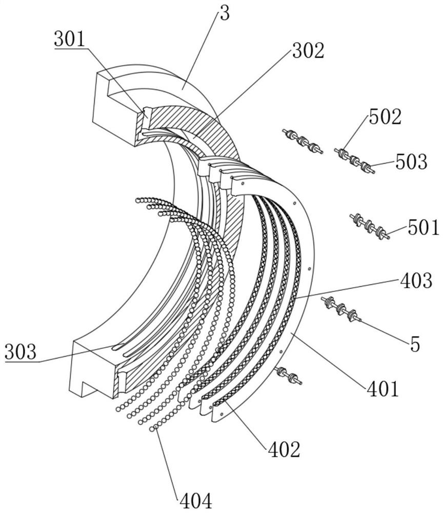
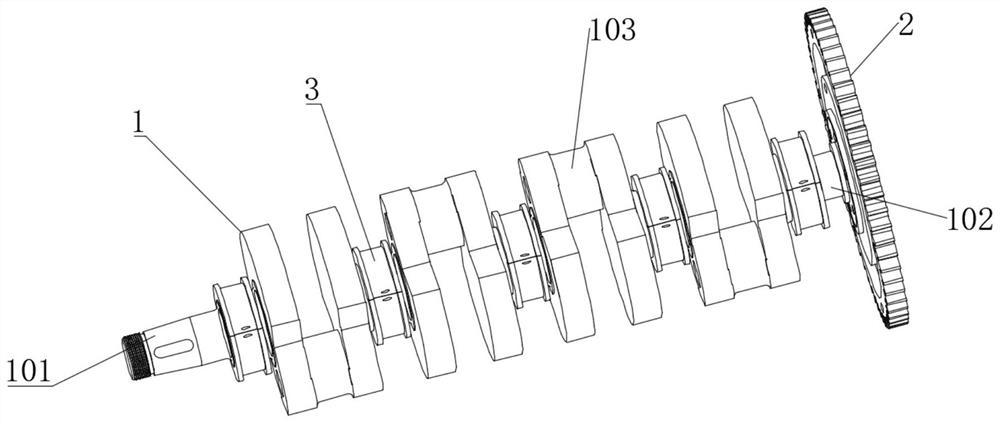
[0052] see Figure 1-10 , a four-cylinder diesel engine crankshaft for preventing shaking, comprising a crankshaft body 1, the crankshaft body 1 includes a main shaft 102, a plurality of eccentrically arranged connecting rod shafts 103 are fixedly connected to the main shaft 102, and the outer ends of the main shaft 102 are fitted with multiple Two main force shaft half sets 3 arranged in pairs, and a plurality of main force shaft half sets 3 arranged in pairs are respectively arranged at intervals with the connecting rod shaft 103, and the inner wall of the main force shaft half sets 3 is equipped with a plurality of anti-shake lubrication components 4, anti-vibration The outer side of the shaking lubrication assembly 4 is connected with a plurality of damage induction assemblies 5 distributed in circular arcs. The anti-shaking lubrication assembly 4 includes an anti-shaking buffer arc bar 401, and the inner wall of the main shaft half sleeve 3 is provided with a plurality of ...

Embodiment 2

[0065] see Figure 1-11 , where the same or corresponding components as those in Embodiment 1 use the corresponding reference numerals as in Embodiment 1, and for the sake of simplicity, only the differences from Embodiment 1 will be described below. The difference between this embodiment 2 and embodiment 1 is: please refer to Figure 11 , the installation method of crankshaft body 1 comprises the following steps:

[0066] S1. Pre-install the main shaft half sleeve 3 located on the lower side to the crankshaft installation place of the fuel engine casing;

[0067] S2. Then install the crankshaft body 1 into the fuel engine casing, and make the main shaft 102 correspond to the main shaft half sleeve 3 located on the lower side, so that the anti-shake buffer arc 401 snaps into the anti-shake groove 104 of the main shaft;

[0068] S3. Finally, install the upper main shaft half sleeve 3 on the main shaft 102 so that the anti-shake buffer arc 401 snaps into the corresponding main...


PUM


Abstract

The invention discloses a four-cylinder crankshaft of a diesel engine that prevents shaking, and belongs to the field of diesel engines. A four-cylinder crankshaft of a diesel engine that prevents shaking includes a crankshaft body, which includes a main shaft, and the main shaft is fixedly connected with a plurality of eccentrically arranged crankshafts. The connecting rod shaft can cooperate with the main shaft half sleeve, the anti-shake lubrication assembly and the crankshaft body, so that the anti-shake buffer arc can buffer the vibration generated by the crankshaft body during the transmission process. Multiple anti-shake lubrication assemblies and the connecting rod The shaft interval is set. In the case of long stroke and large cylinder diameter, the anti-shake buffer arc effectively stabilizes the crankshaft body, improves the transmission accuracy of the crankshaft body, reduces the occurrence of cylinder motion stuttering, and improves the working efficiency of the diesel engine. Ensure the service life of the crankshaft body, and change the surface contact to electrical contact through the anti-friction steel ball to reduce friction, effectively improve the energy conversion rate of the diesel engine, and improve the energy utilization rate.

Description

technical field [0001] The invention relates to the field of diesel engines, more specifically, to a four-cylinder crankshaft of a diesel engine capable of preventing shaking. Background technique [0002] A diesel engine is an internal combustion engine that uses diesel as fuel. The diesel engine is a compression ignition engine, and it is often called the Diesel engine after the main inventor Diesel. When the diesel engine is working, the air sucked into the cylinder of the diesel engine is compressed to a high degree due to the movement of the piston, reaching a high temperature of 500-700°C. Then the fuel is sprayed into the high-temperature air in the form of mist, and mixed with the high-temperature air to form a combustible mixture, which automatically ignites and burns. The energy released in the combustion acts on the top surface of the piston, pushing the piston and converting it into mechanical work of rotation through the connecting rod and crankshaft. [0003...

Claims


Application Information

Patent Timeline
Patent Type & Authority Patents(China)
IPC IPC(8): F16C3/10F16N1/00F16F15/02F16N39/06F16N29/04
CPCF16C3/10F16F15/02F16N1/00F16N29/04F16N39/06
Inventor 殷文元谢善忠
Owner JIANGSU WANLI MACHINERY
Why Eureka
Try Eureka