Fixing device for notebook computer cooling rack for software technology development
A software technology development, notebook computer technology, applied in the direction of machine/support, electrical digital data processing, digital data processing parts, etc., can solve the problems of poor stability, lack of fixation, lack of heat dissipation of notebook computers, etc., and achieve accelerated flow speed , good heat dissipation effect, avoid the effect of overheating
- Summary
- Abstract
- Description
- Claims
- Application Information
AI Technical Summary
Problems solved by technology
Method used
Image
Examples
Embodiment 1
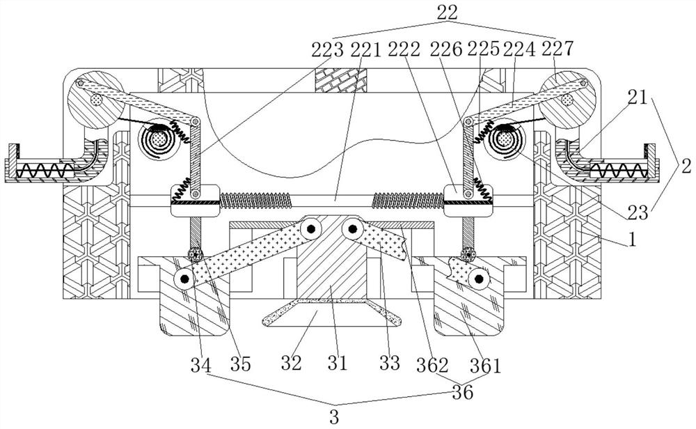
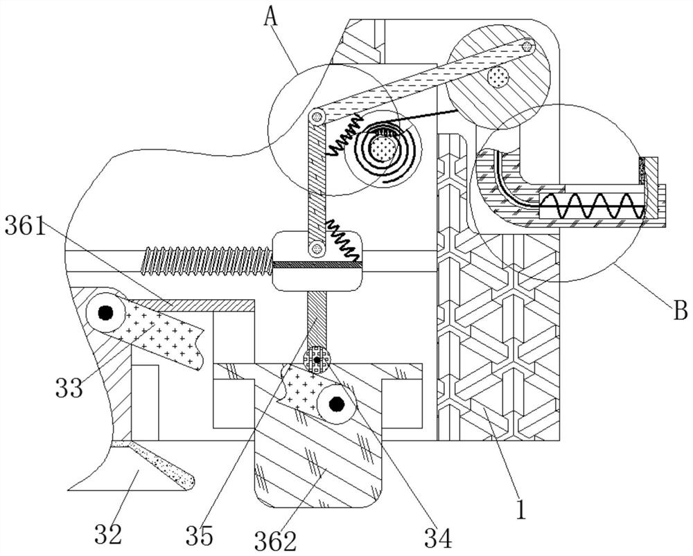
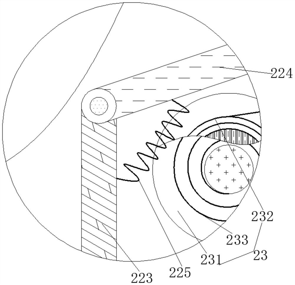
[0024] see Figure 1-4 , a fixing device for a notebook computer heat sink used for software technology development, including a body 1, the inside of the body 1 is movably connected with a clamping mechanism 2 for clamping and fixing the notebook computer, and the clamping mechanism 2 includes a curved rod 21, The outside of the curved rod 21 is movably connected with a transmission assembly 22 that transmits power to the curved rod 21 , and the outside of the curved rod 21 is movably connected with an auxiliary assembly 23 that assists the curved rod 21 in clamping and fixing.
[0025] The transmission assembly 22 comprises a threaded rod 221, the outer surface of the threaded rod 221 is threadedly connected with a moving block 222, the outer surface of the threaded rod 221 is rotatably connected with a connecting rod 223, and the outer surface of the connecting rod 223 is rotatably connected with a pull rod 224, and the outer surface of the pull rod 224 Side rotation is con...
Embodiment 2
[0028] see Figure 1-2 , a fixing device for a notebook computer heat sink used for software technology development, including a body 1, the inside of the body 1 is movably connected with a clamping mechanism 2 for clamping and fixing the notebook computer, and the clamping mechanism 2 includes a curved rod 21, The outside of the curved rod 21 is movably connected with a transmission assembly 22 that transmits power to the curved rod 21 , and the outside of the curved rod 21 is movably connected with an auxiliary assembly 23 that assists the curved rod 21 in clamping and fixing.
[0029] The bottom of moving block 222 is movably connected with fixed mechanism 3, and fixed mechanism 3 comprises connecting plate 31, and the bottom of connecting plate 31 is fixedly connected with adsorption cover 32, and the outer surface of connecting plate 31 is connected with depression bar 33 in rotation, and the bottom of moving block 222 A vertical rod 35 is fixedly connected, the outer sur...
Embodiment 3
[0033] see Figure 1-4, a fixing device for a notebook computer heat sink used for software technology development, including a body 1, the inside of the body 1 is movably connected with a clamping mechanism 2 for clamping and fixing the notebook computer, and the clamping mechanism 2 includes a curved rod 21, The outside of the curved rod 21 is movably connected with a transmission assembly 22 that transmits power to the curved rod 21 , and the outside of the curved rod 21 is movably connected with an auxiliary assembly 23 that assists the curved rod 21 in clamping and fixing.
[0034] The transmission assembly 22 comprises a threaded rod 221, the outer surface of the threaded rod 221 is threadedly connected with a moving block 222, the outer surface of the threaded rod 221 is rotatably connected with a connecting rod 223, and the outer surface of the connecting rod 223 is rotatably connected with a pull rod 224, and the outer surface of the pull rod 224 Side rotation is conn...
PUM
 Abstract
Description
Claims
Application Information
 - R&D
- Intellectual Property
- Life Sciences
- Materials
- Tech Scout
- Unparalleled Data Quality
- Higher Quality Content
- 60% Fewer Hallucinations
Browse by: Latest US Patents, China's latest patents, Technical Efficacy Thesaurus, Application Domain, Technology Topic, Popular Technical Reports.
© 2025 PatSnap. All rights reserved.Legal|Privacy policy|Modern Slavery Act Transparency Statement|Sitemap|About US| Contact US: help@patsnap.com


