Gas turbine combustor nozzle and method for premixing fuel and air in nozzle

A gas turbine and combustion chamber technology, which is applied to combustion methods, combustion chambers, continuous combustion chambers, etc., can solve the problems of insufficient number of fuel holes on rotating blades, high flame combustion temperature, and high NOx emission, and achieves improvement of thermoacoustic oscillation. Characteristics, shortened axial length, effect of simple combustion chamber structure

Active Publication Date: 2021-07-09
CHINA UNITED GAS TURBINE TECH CO LTD
View PDF8 Cites 10 Cited by
  • Summary
  • Abstract
  • Description
  • Claims
  • Application Information

AI Technical Summary

Problems solved by technology

[0004] The disadvantage of this prior art is that, limited by mechanical processing, the number of fuel holes on the rotating blades cannot be too many, and the positions of the openings cannot be too close to the inner and outer surfaces of the premixing channel, thus causing the inner and outer surfaces of the premixing channel The fuel concentration near the wall is relatively high, the flame combustion temperature is high, and the heat release is relatively concentrated. When the gas turbine operates at the base load, the NOx emission is relatively high

Method used


Image

  • Gas turbine combustor nozzle and method for premixing fuel and air in nozzle
  • Gas turbine combustor nozzle and method for premixing fuel and air in nozzle
  • Gas turbine combustor nozzle and method for premixing fuel and air in nozzle

Examples


Embodiment 1

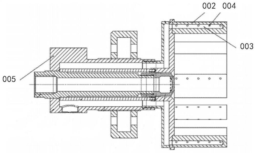
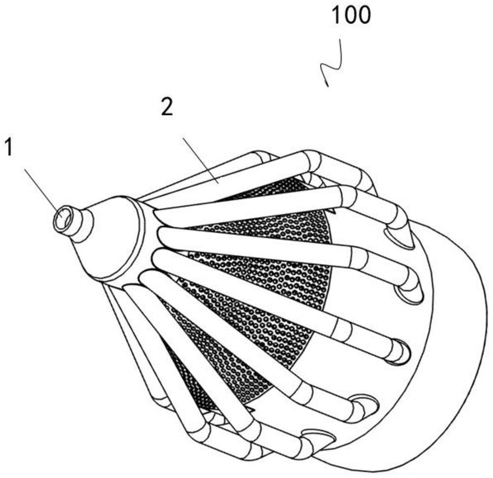
[0065] Depend on Figure 3-4 As shown, the gas turbine combustor nozzle 100 is divided into three parts, which are a fuel delivery main pipe 1 , a fuel flow channel 2 and a fuel-air premixing pipe 3 .

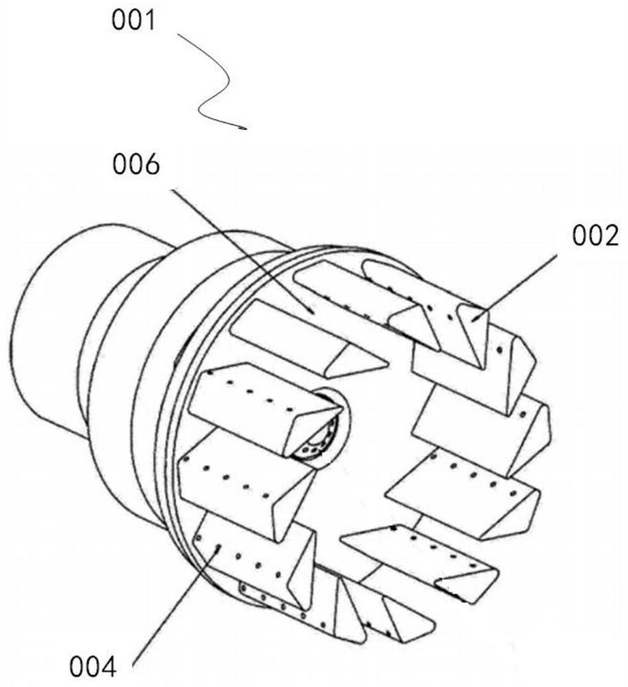
[0066] The diameter of the fuel delivery main pipe 1 changes from small to large according to the fuel flow direction. On the cylindrical structure with a fixed radius of the fuel delivery main pipe 1, a number of fuel outlet holes 12 are arranged in the circumferential direction, and the fuel outlet holes 12 are equidistant in a circular shape. Evenly distributed, each fuel outlet hole 12 corresponds to at least one fuel flow channel 2 . The fuel flow channels 2 are radially arranged with the axis of the fuel delivery main pipe 1 as the geometric center. The fuel flow channels 2 on the same ring layer are at the same axis angle as the fuel delivery main pipe 1 .

[0067] There are several fuel-air premixing pipes 3 , which are evenly distributed in multiple rows along the ra...

Embodiment 2

[0074] Depend on Figure 3-4 As shown, the gas turbine combustor nozzle 100 is divided into three parts, which are a fuel delivery main pipe 1 , a fuel flow channel 2 and a fuel-air premixing pipe 3 .

[0075] The diameter of the fuel delivery main pipe 1 changes from small to large according to the fuel flow direction. On the cylindrical structure with a fixed radius of the fuel delivery main pipe 1, a number of fuel outlet holes 12 are arranged in the circumferential direction, and the fuel outlet holes 12 are equidistant in a circular shape. Evenly distributed, each fuel outlet hole 12 corresponds to at least one fuel flow channel 2 . The fuel flow channels 2 are radially arranged with the axis of the fuel delivery main pipe 1 as the geometric center. The fuel flow channels 2 on the same ring layer are at the same axis angle as the fuel delivery main pipe 1 .

[0076] There are several fuel-air premixing pipes 3 , which are evenly distributed in multiple rows along the ra...

Embodiment 3

[0082] Depend on Figure 3-4 As shown, the gas turbine combustor nozzle 100 is divided into three parts, which are a fuel delivery main pipe 1 , a fuel flow channel 2 and a fuel-air premixing pipe 3 .

[0083] The diameter of the fuel delivery main pipe 1 changes from small to large according to the fuel flow direction. On the cylindrical structure with a fixed radius of the fuel delivery main pipe 1, a number of fuel outlet holes 12 are arranged in the circumferential direction, and the fuel outlet holes 12 are equidistant in a circular shape. Evenly distributed, each fuel outlet hole 12 corresponds to at least one fuel flow channel 2 . The fuel flow channels 2 are radially arranged with the axis of the fuel delivery main pipe 1 as the geometric center. The fuel flow channels 2 on the same ring layer are at the same axis angle as the fuel delivery main pipe 1 .

[0084] There are several fuel-air premixing pipes 3 , which are evenly distributed in multiple rows along the ra...


PUM


Abstract

The invention provides a gas turbine combustor nozzle and a method for premixing fuel and air in the nozzle. The gas turbine combustor nozzle comprises a fuel conveying header pipe, fuel flow channels and fuel and air premixing pipes. The fuel conveying header pipe is provided with a plurality of fuel outlet holes, and each fuel outlet hole corresponds to at least one fuel flow channel. The multiple fuel and air premixing pipes are arranged and provided with fuel spray holes. Fuel enters the fuel conveying header pipe, enters the fuel flow channels through the fuel outlet holes, enters the fuel and air premixing pipes through the fuel spray holes and is mixed with air entering the fuel and air premixing pipes in advance to form a mixture, and the mixture is sprayed out of the fuel and air premixing pipes. According to the gas turbine combustor nozzle and the method for premixing the fuel and the air in the nozzle, the whole nozzle has good fuel and air premixing uniformity.

Description

technical field [0001] The invention relates to the field of gas turbines, in particular to a gas turbine combustion chamber nozzle and a method for premixing fuel and air in the nozzle. Background technique [0002] In gas turbine DLN (Dry Low NOx, dry low nitrogen burner) combustor, the uniformity of fuel and air premixing is a key factor to control combustion NOx emissions. Since the gas turbine combustor mainly contains thermal NOx, its amount is closely related to the combustion temperature. Therefore, when the average combustion temperature is the same, the mixing uniformity of fuel and air is different, causing the local combustion temperature in different regions to deviate from the average temperature, some places are higher and some places are lower. In areas with relatively high temperatures, a large amount of thermal NOx is generated, which eventually leads to a significant increase in NOx emissions at the outlet. [0003] The gas turbine combustor nozzles in t...

Claims


Application Information

Patent Timeline
Patent Type & Authority Applications(China)
IPC IPC(8): F23R3/38F23R3/28
CPCF23R3/38F23R3/286
Inventor 赵光军崔玉峰王昆薛彧
Owner CHINA UNITED GAS TURBINE TECH CO LTD
Why Eureka
Try Eureka