Aperture type air regulation door

A technology for adjusting dampers and apertures, applied to sliding valves, valve details, engine components, etc., can solve the problems of non-quantifiable adjustment angles, increased air leakage, extrusion deformation, etc., to eliminate a large amount of air leakage, reduce air leakage, and compact stacking Effect

Pending Publication Date: 2018-11-13
JIANGSU YONGSHENG OCEAN ENG CO LTD
View PDF0 Cites 6 Cited by
  • Summary
  • Abstract
  • Description
  • Claims
  • Application Information

AI Technical Summary

Problems solved by technology

[0003] 1. The gap between the blade and the inner wall of the pipeline is relatively large, resulting in a large relative air leakage (generally ≥8-10% after testing), so that the ventilation cannot be well blocked
The reason for this problem is that because the damper blade rotates smoothly in the pipeline, there must be a gap between the blade and the inner wall of the pipeline. In addition, the installation tolerance in the production process will make it impossible for the blade to be in contact with the inner wall of the pipeline. Tight fit
[0004] Second, the blades have poor resistance to high wind pressure
The blades of the damper are generally made of 1-2mm thin plates, and the area fixed on the rotating shaft is small, so in actual production, other structures cannot be used to strengthen the supporting blades
In the pipeline with high wind pressure, the blades of the damper are easily squeezed and deformed, which greatly increases the air leakage
[0005] 3. Generally, the damper is adjusted by adjusting the outer actuator, but when adjusting the outer actuator, because it is impossible to accurately know the angle at which the blades in the pipeline turn, the adjustment angle is also random and unquantifiable, and it is impossible to accurately adjust the air volume.

Method used


Image

  • Aperture type air regulation door
  • Aperture type air regulation door
  • Aperture type air regulation door

Examples


Embodiment Construction

[0032] The present invention will be further described below in conjunction with the accompanying drawings and specific embodiments.

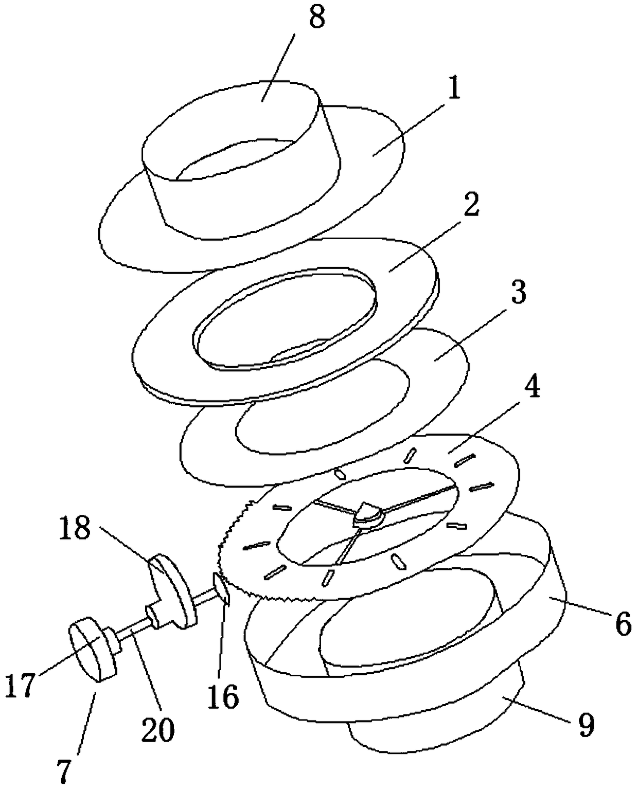
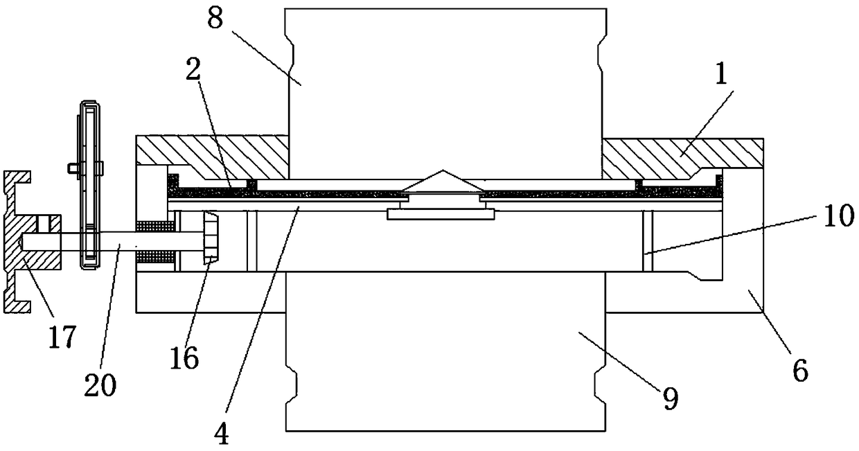
[0033] A diaphragm-type damper, comprising a left side plate 1, a blade positioning ring 2, an arc-shaped blade 3, a gear adjustment disc 4, an air guide 5, a body shell 6, and an actuator 7;

[0034] The upper air pipe joint 8, the lower air pipe joint 9, and the body shell 6 are all pressed and formed on the hydraulic press;

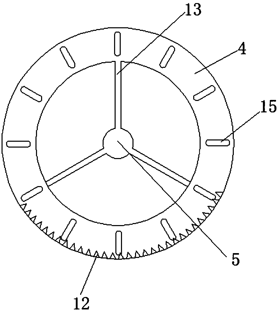
[0035] The lower end surface of the body shell 6 is provided with a down-air pipe joint 9, and the down-air pipe joint 9 communicates with the body shell 6; the upper end surface of the body shell 6 is welded with a support ring 10, and the support ring 10 is provided with a gear adjustment disc 4, and the support ring 10 starts from To support the role of the gear adjusting disc 4; the lower end surface of the gear adjusting disc 4 is provided with an end gear 12, the end gear 12 is an incomplete gear, and the central ...


PUM


Abstract

The invention provides an aperture type air regulation door which comprises a left side plate, a blade positioning ring, arc-shaped blades, a gear regulation disc, an air guiding head, a body shell and an actuator, wherein the arc-shaped blades do not need axial rotation, do not have friction or jam with the inner wall of a pipeline, so that the clearance between each of the arc-shaped blades andthe inner wall of the pipeline is widened; the arc-shaped blades are folded at the air guiding head, one end of each of the arc-shaped blades is closely embedded into an annular groove of the air guiding head, and the arc-shaped blades are closely stacked, so that the air leakage is effectively reduced; a plurality of stems and the annular groove jointly support the blades on a leeside, so that the arc-shaped blades have higher capacity of resisting high wind pressure impact; a pointer and a dial are mounted on a gear box, the rotating radian of the pointer and that of each of the arc-shaped blades in the air regulation door are synchronous, the folding or unfolding degree of the blades of the air regulation door can be visually reflected, and the air volume in the pipeline can be precisely adjusted.

Description

technical field [0001] The invention relates to the technical field of air volume adjustment, in particular to an aperture type damper. Background technique [0002] The damper is also called the air volume control valve, which is widely used in the ventilation piping system of industrial plants, civil buildings, offshore platforms, ships, etc. It is an indispensable end fitting in the process of air conditioning and air purification. The damper can be used not only to adjust the air volume of the branch pipe, but also to adjust the mixing of fresh air and return air. Common damper structures on the market today are as follows: figure 1 As shown, one or more circular blades are fixed on a round shaft by means of bolts or welding, and the rotation of the external adjustment mechanism drives the rotating shaft to change the angle of the blades in the pipeline to change the pipeline. The ventilation area inside, thus changing the air volume flowing through the pipeline. Howe...

Claims


Application Information

Patent Timeline
Patent Type & Authority Applications(China)
IPC IPC(8): F16K3/03F16K3/314F16K31/53F16K37/00
CPCF16K3/03F16K3/314F16K31/535F16K37/0016
Inventor 陈乔峰马长明陈镕坤马洋
Owner JIANGSU YONGSHENG OCEAN ENG CO LTD
Why Eureka
Try Eureka