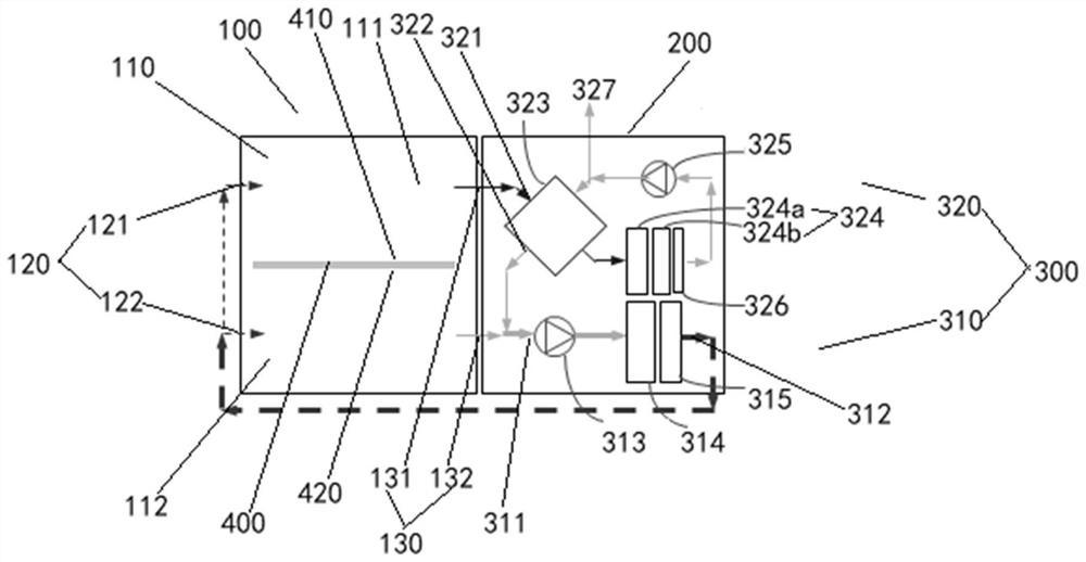
Coating machine drying oven and coating machine waste gas recovery system
A coating machine and oven technology, which is applied to the device for coating liquid on the surface, coating, surface pretreatment, etc., can solve the problems of complicated air volume adjustment, energy waste, and time-consuming in the saving oven, and reduce ineffectiveness. The effect of reducing the operating time, reducing the long construction period and reducing equipment costs
- Summary
- Abstract
- Description
- Claims
- Application Information
AI Technical Summary
Problems solved by technology
Method used
Image
Examples
Embodiment 1
[0043] image 3 It is a schematic diagram of the principle of the coating machine oven provided in the first embodiment of the present application, refer to image 3 As shown, the coating machine oven generally includes a first box body 100 , a second box body 200 and a supply air recovery device 300 . Wherein, the air supply recovery device 300 is integrated and disposed inside the second box body 200 . A drying area 110 is defined inside the first box body 100 , and the drying area 110 is used to allow the target product after coating the slurry to pass through, so as to realize the target product after coating the slurry with the cooperation of the air supply recovery device 300 Drying and recycling of organic gases such as NMP generated during the drying process. The first box body 100 is provided with a drying air inlet 120 and an exhaust gas outlet 130. As a preferred example, the drying air inlet 120 and the exhaust gas outlet 130 can be respectively opened on the opp...
Embodiment 2
[0059] The second embodiment is another preferred embodiment in the industry, and the difference from the first embodiment is that refer to Figure 4 As shown, the first exhaust gas outlet 131 is in communication with the high temperature gas inlet of the heat exchanger 323 and the inlet of the circulating fan 313 .
[0060] Further reference Figure 4 As shown, a part of the high-temperature exhaust gas generated in the first drying area 111 enters the high-temperature gas inlet of the heat exchanger 323 from the first exhaust gas outlet 131, and passes through the heat exchanger 323, the condenser 324, the mist eliminator 326 and the processing fan 325. The formed organic gas heat exchange-condensation recovery circulation flow path is processed for organic gas recovery, and another part of the high-temperature exhaust gas generated in the first drying area 111 is generated from the first exhaust gas outlet 131 and the high-temperature exhaust gas generated in the second dry...
Embodiment 3
[0062] The third embodiment is the third preferred embodiment in the industry, and the difference from the first embodiment is that refer to Figure 5 As shown, the first exhaust gas outlet 131 is communicated with the inlet of the circulating fan 313, and the outlet of the circulating fan 313 is communicated with the high-temperature gas inlet of the heat exchanger 323, that is, the first exhaust gas outlet 131, the second exhaust gas outlet 132 and the recovery outlet The air ports 322 are all communicated with the recovery air inlet through the circulating fan 313 , so that part of the return air is returned to the high temperature gas inlet of the heat exchanger 323 of the recovery component 320 . Disposing the return air returning to the high temperature gas inlet of the heat exchanger 323 downstream of the circulation fan 313 can prevent the circulation fan 313 from interfering with the inlet of the treatment fan 325 in the recovery assembly 320 . However, it should be u...
PUM
 Abstract
Description
Claims
Application Information
 - R&D
- Intellectual Property
- Life Sciences
- Materials
- Tech Scout
- Unparalleled Data Quality
- Higher Quality Content
- 60% Fewer Hallucinations
Browse by: Latest US Patents, China's latest patents, Technical Efficacy Thesaurus, Application Domain, Technology Topic, Popular Technical Reports.
© 2025 PatSnap. All rights reserved.Legal|Privacy policy|Modern Slavery Act Transparency Statement|Sitemap|About US| Contact US: help@patsnap.com


