Power distribution cabinet with heat dissipation function for automobile manufacturing factory

A technology for automobile manufacturing and power distribution cabinets, applied in substation/distribution device casings, electrical components, substation/switch layout details, etc. , difficult to extract moisture and other problems, to achieve the effect of ensuring service life, increasing residence time, and ensuring heat exchange efficiency

Active Publication Date: 2021-07-09
DESIGN INST NO 9 MINISTRY OF MECHINE BUILDING
View PDF11 Cites 0 Cited by
  • Summary
  • Abstract
  • Description
  • Claims
  • Application Information

AI Technical Summary

Problems solved by technology

[0006] In order to solve the above-mentioned technical problems, the present invention provides a power distribution cabinet with heat dissipation function for automobile manufacturing plants, so as to solve the problem that during the use of the existing power distribution cabinets, the heat dissipation device is usually installed on the upper end of the cabinet body. The method of direct pumping determines that the moisture is difficult to extract. Over time, a hot flash environment will be formed in the cabinet, and the inhaled air will aggravate the hot flash phenomenon when the humidity is high. In addition, The straight up and down way makes the heat exchange efficiency between the cool air and the electrical components in the power distribution cabinet in a low state

Method used


Image

  • Power distribution cabinet with heat dissipation function for automobile manufacturing factory
  • Power distribution cabinet with heat dissipation function for automobile manufacturing factory
  • Power distribution cabinet with heat dissipation function for automobile manufacturing factory

Examples


Embodiment

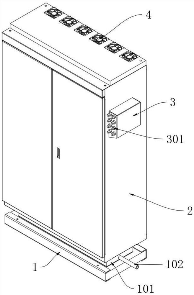
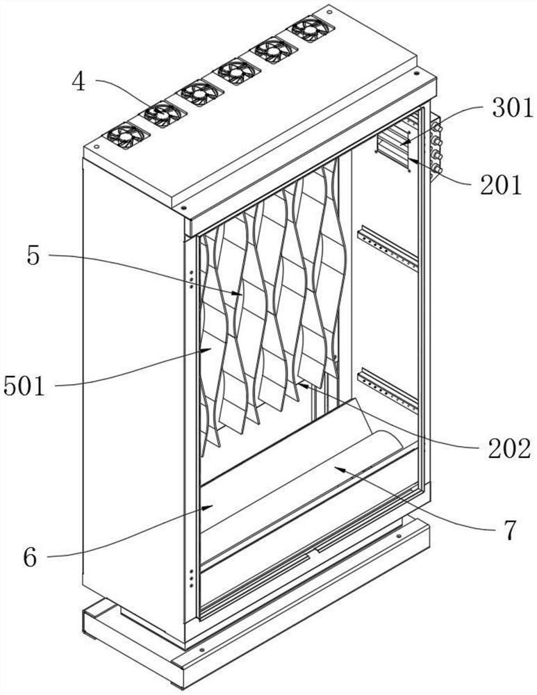
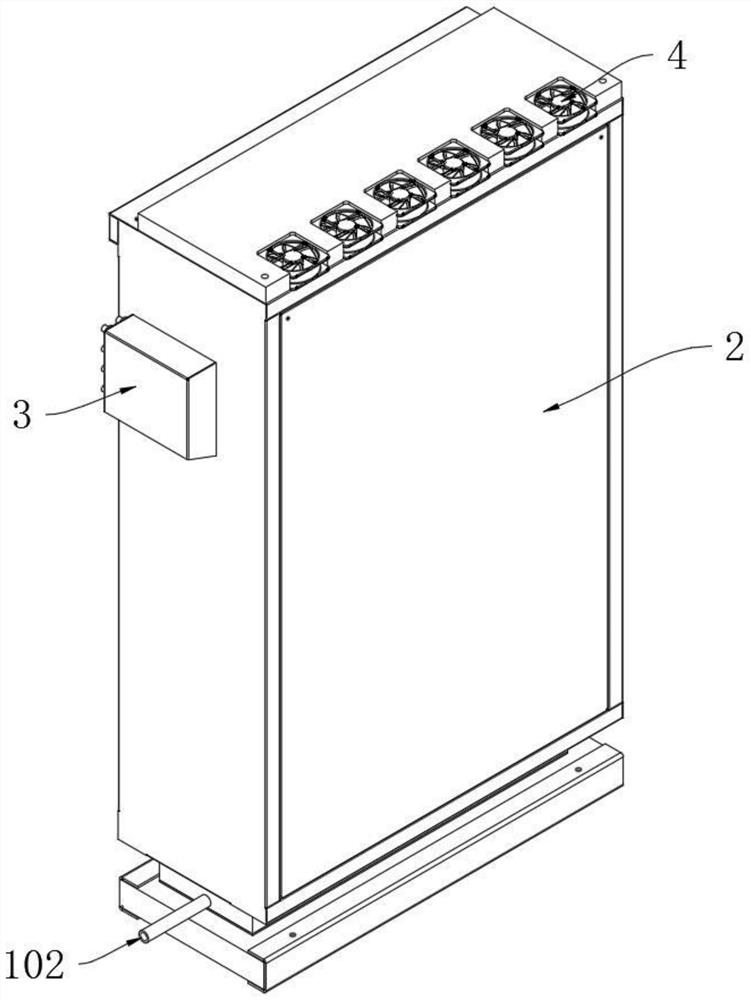
[0032] as attached figure 1 to attach Figure 6 Shown:

[0033] The invention provides a power distribution cabinet for automobile manufacturing plants with heat dissipation function, which includes a base 1, a cuboid power distribution cabinet main body 2 is fixedly installed on the upper end of the base 1, and the middle part of the right end side wall of the power distribution cabinet main body 2 is near the upper part The air intake filter box 3 is fixedly installed, and the inner end of the air intake filter box 3 is connected with the inner cavity of the main body 2 of the power distribution cabinet. There are 2-6 fixed and fixed installations at the rear edge of the top plane of the main body 2 of the power distribution cabinet. There are 6 cooling fans 4 arranged side by side in this embodiment. In the inner cavity of the main body 2 of the power distribution cabinet below the heat dissipation fan 4, a heat dissipation conversion backplane 5 is vertically fixedly ins...


PUM


Abstract

The invention provides a power distribution cabinet with a heat dissipation function for an automobile manufacturing factory, relates to the technical field of power distribution cabinets, and aims to solve the problems that in the use process of the conventional power distribution cabinet, generally, a heat dissipation device is mostly arranged at the upper end of a cabinet body, and in addition, the heat exchange efficiency of cool air and electric elements in the power distribution cabinet is in a lower state in a vertical up-down mode. The power distribution cabinet comprises a base, a cuboid power distribution cabinet main body is fixedly mounted at the upper end of the base; an air inlet filter box is fixedly mounted at the middle upper part of the right end side wall of the power distribution cabinet main body; the inner end of the air inlet filter box is communicated with the inner cavity of the power distribution cabinet main body; and 2-6 side-by-side heat dissipation fans are uniformly and fixedly arranged on the rear end edge of the top plane of the power distribution cabinet main body at intervals. External cool air enters from the air inlet, flows downwards from the upper part of the inner cavity of the power distribution cabinet main body, and is discharged into the water accumulation box through the water return hole for centralized collection, so that the normal use of the heat dissipation fan is prevented from being influenced, and the heat dissipation efficiency is ensured.

Description

technical field [0001] The present invention relates to the technical field of power distribution cabinets, and more specifically relates to a power distribution cabinet for automobile manufacturing plants with heat dissipation function. Background technique [0002] With the rapid development of my country's social economy, more and more vacant land has been developed, more and more places need power distribution, the demand for power distribution cabinets is increasing, and the environment in which power distribution cabinets are located is becoming more and more complex. The more complex it is, the higher the workload required, and it is a necessary tool for the normal development of society today. [0003] For example, in the patent application CN201810268063.3, a power distribution cabinet with heat dissipation function includes a shell, and a power distribution equipment compartment is arranged inside the shell, and a water cooling compartment is arranged below the powe...

Claims


Application Information

Patent Timeline
IPC IPC(8): H02B1/30H02B1/28H02B1/56
CPCH02B1/30H02B1/28H02B1/565
Inventor 马明星马呈宇向桐
Owner DESIGN INST NO 9 MINISTRY OF MECHINE BUILDING
Why Eureka
Try Eureka