Metal foil, metal foil with carrier, copper-clad laminated plate, and printed wiring board

A carrier metal and metal foil technology, which is applied to printed circuit components, circuit devices, etc., can solve the problem that the high-frequency signal transmission loss and peel strength of the metal foil cannot be taken into account at the same time

Active Publication Date: 2021-07-09
GUANGZHOU FANGBANG ELECTRONICS
View PDF11 Cites 3 Cited by
  • Summary
  • Abstract
  • Description
  • Claims
  • Application Information

AI Technical Summary

Problems solved by technology

That is, the two requirements of the existing technology on the surface morphology of the metal foil are contradictory, and it is impossible to take into account the high-

Method used


Image

  • Metal foil, metal foil with carrier, copper-clad laminated plate, and printed wiring board
  • Metal foil, metal foil with carrier, copper-clad laminated plate, and printed wiring board
  • Metal foil, metal foil with carrier, copper-clad laminated plate, and printed wiring board

Examples


Embodiment Construction

[0057] The following will clearly and completely describe the technical solutions in the embodiments of the present invention with reference to the accompanying drawings in the embodiments of the present invention. Obviously, the described embodiments are only some, not all, embodiments of the present invention. Based on the embodiments of the present invention, all other embodiments obtained by persons of ordinary skill in the art without creative efforts fall within the protection scope of the present invention.

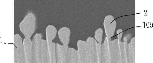
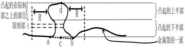
[0058] refer to figure 1 As shown, the embodiment of the present invention provides a metal foil 1, a plurality of protrusions 2 are distributed on one side of the metal foil 1, and the protrusions 2 have the following microscopic appearance: see figure 2 , the lower half of the protrusion 2 connected to the one side of the metal foil 1 has a restriction part 100, and the diameter of the circumscribed circle of the cross section of the restriction part 100 is smal...


PUM

PropertyMeasurementUnit
Heightaaaaaaaaaa

Abstract

The invention discloses a metal foil, a metal foil with a carrier, a copper-clad laminated plate and a printed circuit board. A plurality of bulges are distributed on one surface of the metal foil, and each bulge has the following microstructure: the lower half part, connected with one surface of the metal foil, of each bulge is provided with a limiting part, the diameter of the circumcircle of the cross section of the limiting part is smaller than the skin depth of the metal foil, and the surface area of the portion, above the limiting portion, of the bulge is larger than the surface area of the other portion of the bulge. By adopting the embodiment of the invention, not only can the high-frequency signal transmission loss of the metal foil be reduced, but also good peeling strength between the signal transmission line formed by the metal foil and the dielectric layer can be realized.

Description

technical field [0001] The invention relates to the field of material technology, in particular to a metal foil, a metal foil with a carrier, a copper-clad laminate and a printed circuit board. Background technique [0002] Printed circuit board (PCB) is widely used in electronic equipment, and with the continuous improvement of the functions of semiconductor electronic components, the integration and data transmission speed of electronic components in electronic equipment are getting higher and higher. In this way, the density of signal transmission lines on the printed circuit board as a signal transmission carrier is getting higher and higher, so that the signal transmission lines are getting thinner and the frequency of the signal current of the signal transmission lines is getting higher and higher. Therefore, the transmission effect of high-frequency signals has become one of the standards for measuring the performance of printed circuit boards. Among them, the struct...

Claims


Application Information

Patent Timeline
IPC IPC(8): H05K1/02
CPCH05K1/0213
Inventor 高强朱宇华张美娟张可蒋卫平朱开辉苏陟
Owner GUANGZHOU FANGBANG ELECTRONICS
Why Eureka
Try Eureka