Anti-blocking die hole structure, stamping lower die and machining technology of dense small meshes

A processing technology and hole structure technology, which is applied in the field of punching processing, can solve the problems of speaker shell mesh burr, small speaker shell blockage, time-consuming and laborious cleaning, etc., to weaken the structural strength, ensure smoothness, and reduce processing time. Effect

Active Publication Date: 2021-07-13
深圳市鹏福创新实业有限公司
View PDF6 Cites 2 Cited by
  • Summary
  • Abstract
  • Description
  • Claims
  • Application Information

AI Technical Summary

Problems solved by technology

[0003] Many boards use the above-mentioned lower die with the die hole 11 of the initial cylindrical section 111 and the blanking conical section 112 in the punching process. However, it is found in the actual production process that in the punching process of the small speaker shell prone to material blockage
On the one hand, the waste material 2 blocked in the die hole 11 not only affects the downward movement of the punch, but also easily causes burrs to appear in the mesh holes processed on the speaker shell; As well as to improve the user experience, the mesh holes on the shell of small speakers are usually small and dense (see Figure 4 Middle G), the die holes 11 of the corresponding lower die are also relatively small and dense, and it is very time-consuming and laborious to clean up

Method used


Image

  • Anti-blocking die hole structure, stamping lower die and machining technology of dense small meshes
  • Anti-blocking die hole structure, stamping lower die and machining technology of dense small meshes
  • Anti-blocking die hole structure, stamping lower die and machining technology of dense small meshes

Examples


Embodiment 1

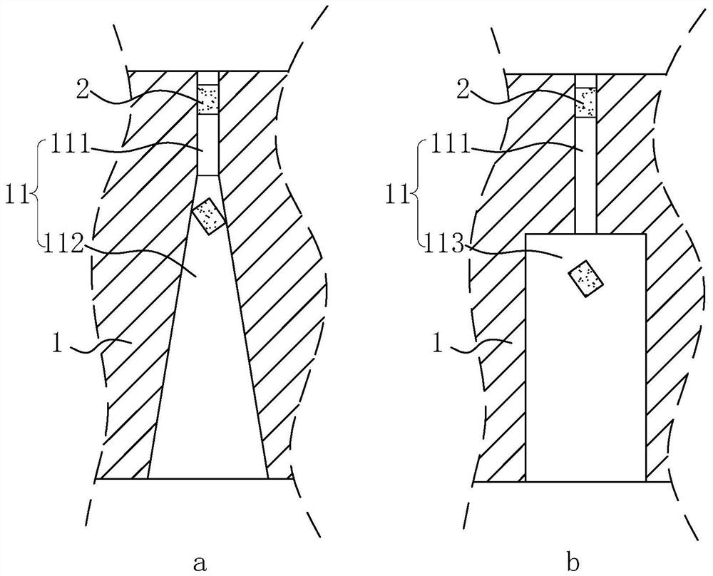
[0044] This embodiment discloses a structure of anti-blocking material die hole 11, refer to figure 1 Middle a is set on the lower mold body 1 , including an upper initial cylindrical section 111 and a lower outwardly expanding blanking cylindrical section 113 .

[0045] The horizontal cross-sectional shape of the initial cylindrical section 111 is adapted to the horizontal cross-sectional shape of the to-be-processed mesh 31 on the workpiece 3 . The depth of the mesh hole 31 to be processed on the workpiece 3 is the same as the height of the corresponding waste material 2 , and the height of the initial cylindrical section 111 is 4 to 6 times the height of the waste material 2 . The horizontal section width of the blanking cylindrical section 113 is 3 to 5 times the height of the waste material 2 .

Embodiment 2

[0047] This embodiment discloses a stamping lower die, and the die hole 11 on the stamping lower die adopts the structure of the anti-blocking die hole 11 in the first embodiment.

Embodiment 3

[0049] This embodiment discloses a processing technology for dense small meshes 31, which adopts the method of dispersing multiple punching processes, that is, the meshes 31 on the processing surface of the workpiece 3 are punched in several times, and the area of ​​each punching is the same as The areas that have been stamped before are staggered, and the areas that are stamped each time are distributed on the processing surface of the workpiece 3, wherein, the lower die used in stamping is the stamping lower die in Example 2.

[0050] the case

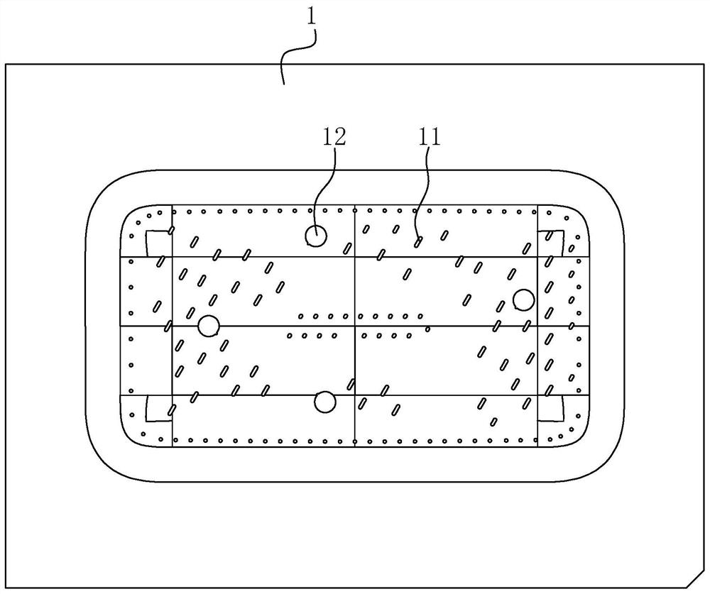
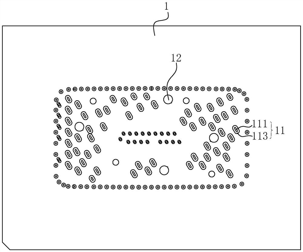
[0051] see Figure 4 In G, the workpiece 3 targeted in this case is the shell of a small mini speaker. The shell of the workpiece 3 is made of aluminum 1050 and has a thickness of 1 mm. It is rectangular in shape with slightly arc-shaped edges on the whole, and a number of dense small meshes 31 are opened on the surface of the shell. The mesh 31 is basically a columnar hole with a waist-shaped horizontal section. In addition, there...


PUM


Abstract

The invention belongs to the technical field of punching machining, and relates to an anti-blocking die hole structure, a stamping lower die and a machining technology of dense small meshes. The anti-blocking die hole structure comprises an initial cylindrical section on the upper portion and an externally-expanded discharging cylindrical section on the lower portion, wherein the horizontal section of the initial cylindrical section is matched with the horizontal section of a to-be-machined mesh of a workpiece, and the width of the section of the discharging cylindrical section is larger than the depth of the to-be-machined mesh of the workpiece. A die hole of the stamping lower die adopts the anti-blocking die hole structure. In the machining process of the dense small meshes, the stamping lower die is adopted, and a scattered multi-time punching machining mode is adopted, that is, the meshes in the machining face of the workpiece are formed through multiple times of stamping, the area stamped each time is staggered from the area where stamping is completed, and the area stamped each time is distributed on the machining face of the workpiece in a scattered mode. The lower die is suitable for machining dense small meshes of soft metal plates, the material blocking phenomenon can be almost completely avoided, burrs are not generated during punching, and the structural strength of the lower die can be guaranteed.

Description

technical field [0001] The application relates to the field of punching processing, in particular to the processing technology of anti-blocking material die hole structure, stamping lower die and dense small mesh. Background technique [0002] The processing holes on the plate usually adopt the punching process, refer to figure 1 In a, the die hole 11 of the lower die of the punching process is usually arranged vertically, and is generally arranged in two sections along the lower die body 1 from top to bottom. The upper section is a horizontal section corresponding to the horizontal section of the workpiece to be processed. Matching the initial cylindrical section 111, the next section is the blanking cone section 112, and the inner space of the blanking cone section 112 gradually becomes larger from top to bottom. The die hole 11 provided by the initial cylindrical section 111 plus the blanking conical section 112, on the one hand, because the inner space of the lower part...

Claims


Application Information

Patent Timeline
Patent Type & Authority Applications(China)
IPC IPC(8): B21D28/34B21D28/26B21D45/00
CPCB21D28/34B21D28/26B21D45/00
Inventor 邵传清李大文
Owner 深圳市鹏福创新实业有限公司
Why Eureka
Try Eureka